Silicon rod splicing method, spliced silicon rod and spliced silicon rod cutting method

A cutting method and technology for silicon rods, which are used in the field of silicon rod splicing, splicing silicon rods and splicing silicon rods, can solve the problems of loss of number of sheets, loss of production capacity, occupation, etc., to reduce adhesion and improve heat resistance. performance, saving operation time

Pending Publication Date: 2021-05-14
LUOYANG CSI PHOTOVOLTAIC TECH CO LTD
View PDF7 Cites 1 Cited by
  • Summary
  • Abstract
  • Description
  • Claims
  • Application Information

AI Technical Summary

Problems solved by technology

However, this cutting process will cause the loss of 6-15 silicon wafers per silicon rod, and the loss of 1-1.5% of the number of wafers produced. The sub

Method used


Image

  • Silicon rod splicing method, spliced silicon rod and spliced silicon rod cutting method
  • Silicon rod splicing method, spliced silicon rod and spliced silicon rod cutting method
  • Silicon rod splicing method, spliced silicon rod and spliced silicon rod cutting method

Examples


Example Embodiment

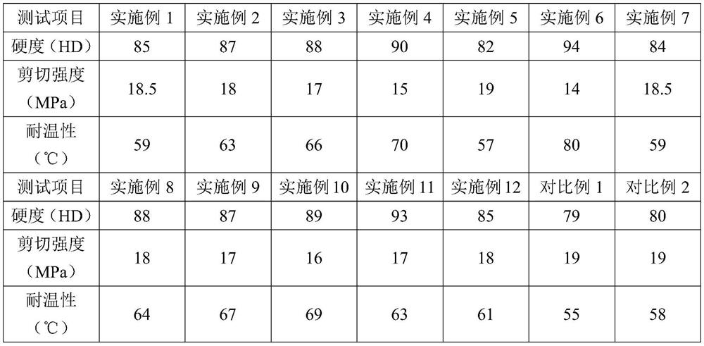
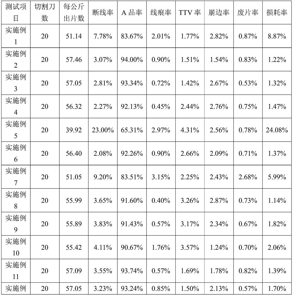
[0035]Example 1

[0036]This embodiment provides a silicon bar stitching method including the following steps:

[0037](1) Filibilicon-containing wastewater produced by the silicon rod is filtered to obtain silicone, and then silicone is baked at 150 ° C for 6 h, ground, to obtain silicon powder (average particle size 0.8 μm);

[0038](2) The silicon powder obtained from the silicon bar adhesive (DL2227) (the silicon powder occupies the silicon bar adhesive and the total mass of the silicon powder is 1%), and the mix is ​​mixed uniform, then coated onto the silicon rod ( Size 157mm × 157mm × 230mm) The three silicars are stitched together on the surface to be spliced;

[0039](3) Curing at room temperature (22 ° C) for 8 h, the silicon rod splicing (2 mm thickness of the rubber layer) was completed.

Example Embodiment

[0040]Example 2

[0041]This embodiment provides a silicon bar splicing method, and the difference from Example 1 is that the silicon powder occupies the total mass of the silicon bar adhesive and the total mass of silicon powder.

Example Embodiment

[0042]Example 3

[0043]This embodiment provides a silicon bar stitching method, and the difference from Example 1 is that the percentage of silicon powder occupies the total mass of silicon rod adhesive and silicon powder is 2.5%.


PUM

PropertyMeasurementUnit
Particle sizeaaaaaaaaaa
The average particle sizeaaaaaaaaaa

Abstract

The invention provides a silicon rod splicing method, a spliced silicon rod and a spliced silicon rod cutting method. The silicon rod splicing method comprises the following steps: mixing a silicon rod adhesive and a filling agent, then coating the mixture on a to-be-spliced surface of a silicon rod, and completing silicon rod splicing after splicing and curing, wherein the filling agent is selected from a combination of one or at least two of silicon powder, iron powder or carbon powder. The cutting method comprises the following steps: loading the spliced silicon rod prepared by the silicon rod splicing method on a machine, and carrying out full-wire net cutting by using a diamond wire. The spliced silicon rod prepared by the silicon rod splicing method provided by the invention can be subjected to full-wire net cutting processing by adopting the diamond wire, so that the adhesion of an adhesive layer at the spliced part of the silicon rod to the diamond wire can be reduced, the wire breaking risk is reduced, and the yield of silicon wafers is improved.

Description

technical field [0001] The invention belongs to the technical field of crystalline silicon cutting and processing, and in particular relates to a silicon rod splicing method, a spliced ​​silicon rod and a cutting method for the spliced ​​silicon rod. Background technique [0002] Diamond wire cutting crystalline silicon is a new type of silicon wafer processing technology developed in recent years. Compared with sand wire cutting (using polyethylene glycol dispersed silicon carbide blades for cutting), it has significant advantages, mainly in high cutting capacity and low environmental pollution. , Less loss of sawing silicon material and so on. At present, diamond wire cutting has developed into the mainstream silicon wafer processing technology, and its production capacity is more than six times higher than that of sand wire cutting. [0003] Crystalline silicon, especially polycrystalline silicon, has a limited crystal growth height during the ingot preparation process. ...

Claims


Application Information

Patent Timeline
IPC IPC(8): B28D5/04B28D7/00
CPCB28D5/045B28D5/0058
Inventor 王珊珊熊震李飞龙
Owner LUOYANG CSI PHOTOVOLTAIC TECH CO LTD
Why Eureka
Try Eureka