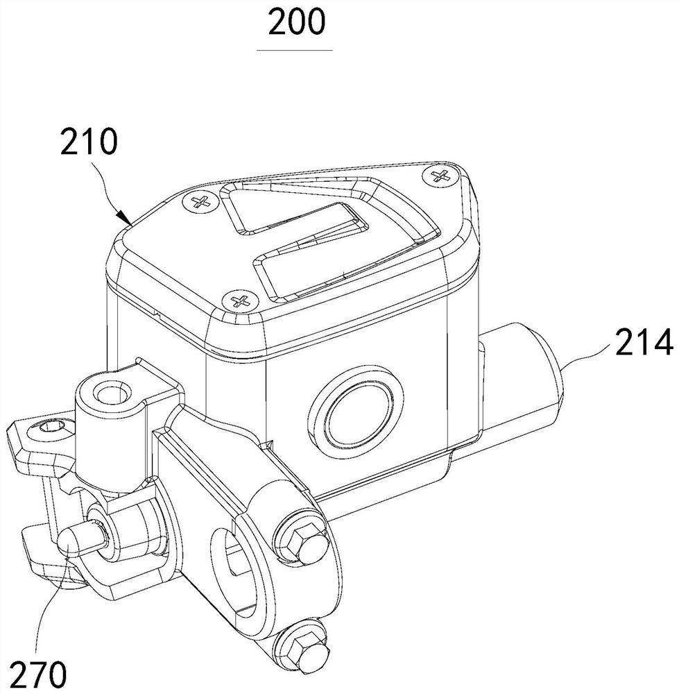
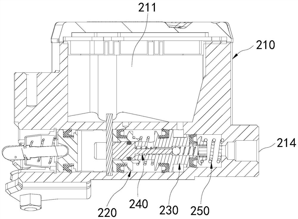
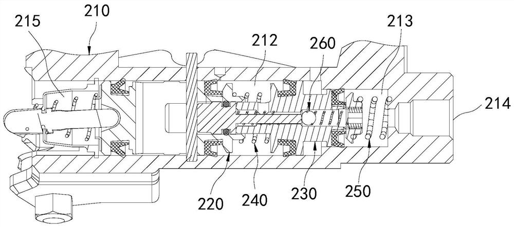
Pressurizing main pump and vehicle hydraulic braking system

A main pump and pump body technology, applied in hydraulic brake transmissions, bicycle brakes, bicycle accessories, etc., can solve problems such as increased grip strength and impact on rider experience.

Pending Publication Date: 2021-05-14
HUBEI HANGTE TECH CO LTD
View PDF0 Cites 0 Cited by
  • Summary
  • Abstract
  • Description
  • Claims
  • Application Information

AI Technical Summary

Problems solved by technology

[0003] This kind of main pump will have such a problem: the size of the brake handle limits the maximum lever ratio of the handle. When the brake system requires the main pump to increase the discharge volume of a single stroke, it must be achieved by increasing the diameter of the main pump piston. This will lead to a sharp increase in grip strength when the hydraulic pressure of the same size is established, which will affect the rider's experience

Method used


Image

  • Pressurizing main pump and vehicle hydraulic braking system
  • Pressurizing main pump and vehicle hydraulic braking system
  • Pressurizing main pump and vehicle hydraulic braking system

Examples


Embodiment Construction

[0045]In order to make the purpose, technical solutions and advantages of the embodiments of the present invention clearer, the technical solutions in the embodiments of the present invention will be clearly and completely described below in conjunction with the drawings in the embodiments of the present invention. Obviously, the described embodiments It is a part of embodiments of the present invention, but not all embodiments. The components of the embodiments of the invention generally described and illustrated in the figures herein may be arranged and designed in a variety of different configurations.

[0046] Accordingly, the following detailed description of the embodiments of the invention provided in the accompanying drawings is not intended to limit the scope of the claimed invention, but merely represents selected embodiments of the invention. Based on the embodiments of the present invention, all other embodiments obtained by persons of ordinary skill in the art wit...


PUM


Abstract

The invention relates to the technical field of braking, and in particular relates to a pressurizing main pump and a vehicle hydraulic braking system. The pressurizing main pump comprises a pump body, a first piston, a second piston, a first elastic piece and a second elastic piece. The pump body is provided with an oil cavity, a first piston cavity and a second piston cavity, the oil cavity is communicated with the first piston cavity, and the pump body is provided with an oil outlet communicated with the second piston cavity; the axis of the first piston cavity coincides with the axis of the second piston cavity, and the inner diameter of the first piston cavity is larger than that of the second piston cavity; the first piston matches the first piston cavity in a sliding manner; the second piston comprises a first branch part and a second branch part, the first branch part matches the second piston cavity in a sliding mode, and the second branch part matches the second piston cavity in a sliding mode; the two ends of the first elastic piece abut against the first piston and the first branch part correspondingly, and the two ends of the second elastic piece abut against the second branch part and the second piston cavity correspondingly. The pressurizing main pump can provide better braking experience for a rider.

Description

technical field [0001] The invention relates to the technical field of braking, in particular to a booster main pump and a vehicle hydraulic braking system. Background technique [0002] At present, most of the hydraulic brake main pumps used in two-wheeled motorcycles on the market have a one-stage piston structure. The working principle is: the brake handle is rotated to push the main pump piston to move, output oil and establish hydraulic pressure. [0003] This kind of main pump will have such a problem: the size of the brake handle limits the maximum lever ratio of the handle. When the brake system requires the main pump to increase the discharge volume of a single stroke, it must be achieved by increasing the diameter of the main pump piston. This will lead to a sharp increase in grip strength when the hydraulic pressure of the same size is established, thereby affecting the rider's experience. Contents of the invention [0004] The purpose of the present invention ...

Claims


Application Information

Patent Timeline
Patent Type & Authority Applications(China)
IPC IPC(8): B60T11/16B62L3/02
CPCB60T11/16B62L3/023
Inventor 杨荣田友平苗壮
Owner HUBEI HANGTE TECH CO LTD
Why Eureka
Try Eureka