Supercharge Your Innovation With Domain-Expert AI Agents!

Electric propeller with two usable faces

An electric propulsion, double-sided technology, applied in the direction of ship propulsion, propulsion components, electric components, etc., can solve problems affecting the propulsion energy efficiency of the propeller, and achieve the effect of improving propulsion efficiency and reducing complexity

Pending Publication Date: 2021-05-14
杭州舟海智能科技有限责任公司
View PDF0 Cites 1 Cited by
  • Summary
  • Abstract
  • Description
  • Claims
  • Application Information

AI Technical Summary

Problems solved by technology

[0008] Aiming at the deficiencies of the prior art, the present invention provides a double-sided electric propeller, which overcomes the deficiencies of the prior art, has a reasonable design and a compact structure, and aims to solve the problems existing in the structure of the traditional propeller: if the motor At the axial center of the flow channel, additional anti-corrosion and impurity prevention measures are required; if the motor is placed at the water inlet of the flow channel, it will affect the energy efficiency of the propeller

Method used


Image

  • Electric propeller with two usable faces
  • Electric propeller with two usable faces
  • Electric propeller with two usable faces

Examples


Embodiment 1

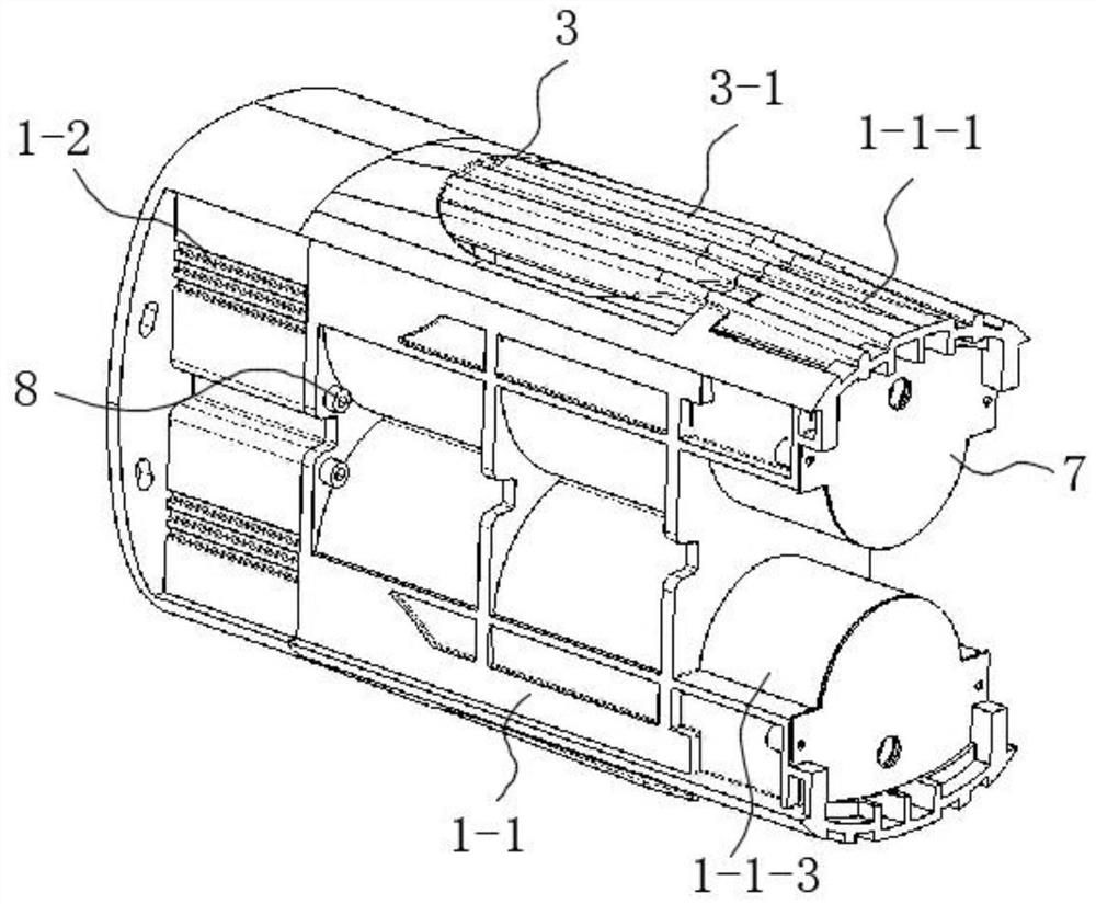
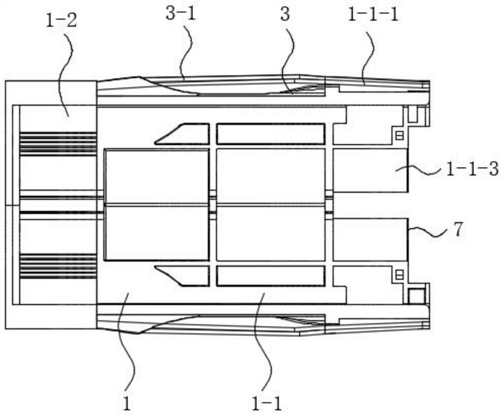
[0038] A double-sided electric propeller includes a body frame 1 as an installation base, the body frame 1 is composed of a front frame 1-1 and a rear frame 1-2, and the front frame 1-1 and the rear frame 1-2 The composition is fixed by screws 8;

[0039] The upper and lower sides of the front frame 1-1 are symmetrically integrally formed with a main channel 1-1-2, and the side of the front frame 1-1 away from the rear frame 1-2 is symmetrically provided with a motor installation cavity 1-1-3, And the outside of the main channel 1-1-2 is open and provided with a water inlet for liquid medium input, and a water inlet grill 3 is arranged on the water inlet;

[0040] The upper and lower sides of the rear frame 1-2 are symmetrically provided with contraction nozzles 1-2-1, and the stator blades 1-2-2 for reinforcement are fixedly installed in the contraction nozzles 1-2-1;

[0041] A motor 2 for generating power is provided in the two motor installation cavities 1-1-3, and the mo...

Embodiment 2

[0045] The difference between this embodiment and embodiment 1 is that, as Figure 6-8 As shown, the side of the water inlet grille 3 close to the front frame 1-1 is symmetrically provided with a first boss 3-2 for positioning, and the front frame 1-1 is symmetrically provided with the first boss 3-2. 2 first grooves 1-1-4 engaged with each other; the side of the rear frame 1-2 close to the water inlet grille 3 is symmetrically provided with a second boss 1-2-3 for positioning, and the water inlet The grid 3 is symmetrically provided with a second groove 3-1 engaging with the second boss 1-2-3;

[0046] In this embodiment, the first boss 3-2 is engaged with the first groove 1-1-4, and the second boss 1-2-3 is engaged with the second groove 3-1, effectively ensuring the water inlet Stable installation of grille 3.

Embodiment 3

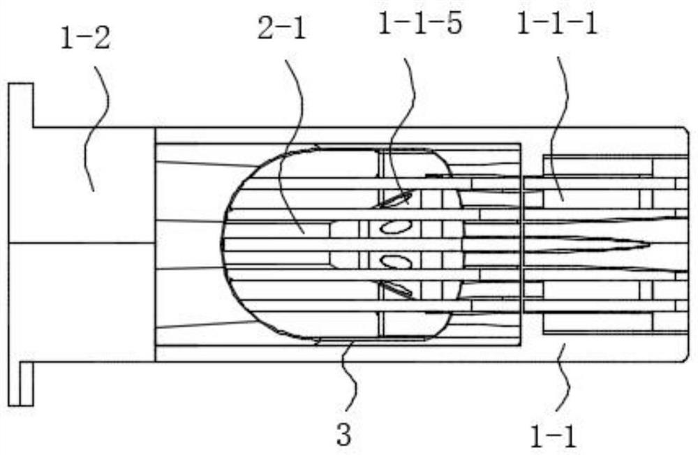
[0048] The difference between this embodiment and embodiment 1 is that, as Figure 4-6 As shown, the side of the main channel 1-1-2 close to the motor installation position is integrally formed with a shaft sleeve part 1-1-5 sleeved on the motor shaft 2-1, and the shaft sleeve part 1-1-5 is There are multiple flow channels connected with the motor installation cavity 1-1-3;

[0049] In this embodiment, the fluid medium passes through the motor installation chamber 1-1-3, so that the heat from the motor 2 in the motor installation chamber 1-1-3 is transferred away, which is beneficial to the heat dissipation of the motor.


PUM


Abstract

The invention relates to the technical field of propellers, provides an electric propeller with two usable faces, and aims to solve the problems that when a traditional propeller is constructed, if a motor is arranged at the axis position of a flow channel, additional treatment means such as corrosion prevention and impurity prevention are needed; and if the motor is arranged at the water inlet of the flow channel, the propulsion efficiency of the propeller is influenced. The electric propeller comprises a machine body frame serving as a mounting base body, the machine body frame is composed of a front frame body and a rear frame body, and the front frame body and the rear frame body are fixed through screws; main flow channels are symmetrically and integrally formed in the upper face and the lower face of the front frame; motor mounting cavities are symmetrically formed in the side, away from the rear frame, of the front frame; water inlets used for inputting liquid media are formed in the outer sides of the main flow channels in an open mode; and water inlet grids are arranged on the water inlets. The electric propeller is especially suitable for improving the propulsion efficiency of water surface and underwater equipment, and has a higher social use value and application prospect.

Description

technical field [0001] The invention relates to the technical field of propellers, in particular to a double-sided electric propeller. Background technique [0002] Propellers, which generate thrust by rotating blades or jets of air (water), are capable of powering surface or submerged equipment to change or maintain their state of motion. [0003] The structural methods mainly included in the electric power arrangement of propellers in related domestic technologies or products are: [0004] 1. The motor is placed at the axial center of the flow channel and close to the direction of the nozzle. This arrangement requires an additional wire tube to guide the motor cable to the desired position through the axis; in order to reduce the length of the flow channel, an external rotor motor is usually used , but the propeller is directly connected to the outer rotor of the motor, which causes the internal iron core and magnetic steel of the motor to be exposed to the fluid medium, ...

Claims


Application Information

Patent Timeline
IPC IPC(8): B63H21/17H02K7/10H02K7/14
CPCB63H21/17H02K7/10H02K7/14
Inventor 赵玉侠
Owner 杭州舟海智能科技有限责任公司
Features
  • R&D
  • Intellectual Property
  • Life Sciences
  • Materials
  • Tech Scout
  • Unparalleled Data Quality
  • Higher Quality Content
  • 60% Fewer Hallucinations
Learn More