Automatic feeding and discharging equipment and automatic feeding and discharging method

An automatic loading and unloading and equipment technology, applied in the direction of conveyor control devices, conveyor objects, transportation and packaging, etc., can solve the problems of unstable production efficiency and product quality, high labor intensity, and manpower occupation, and achieve equipment operation and The effect of flexible control, stable equipment operation, and convenient loading and unloading

Pending Publication Date: 2021-05-14
XIAMEN HONGXIN ELECTRON TECH +1
View PDF0 Cites 2 Cited by
  • Summary
  • Abstract
  • Description
  • Claims
  • Application Information

AI Technical Summary

Problems solved by technology

[0002] With the technological development of intelligent manufacturing and the needs of industrial upgrading, manual operation is developing towards semi-automatic equipment, and semi-automatic equipment is developing towards fully automated equipment. However, early manufacturing companies have purchased multiple semi-automatic equipment, and one person operates one equipment for semi-automatic equipment. , more labor-intensive, manual operation is labor-intensive, prone to fatigue, production efficiency and product quality are unstable

Method used


Image

  • Automatic feeding and discharging equipment and automatic feeding and discharging method
  • Automatic feeding and discharging equipment and automatic feeding and discharging method
  • Automatic feeding and discharging equipment and automatic feeding and discharging method

Examples


Embodiment Construction

[0053] In order to further explain the technical solution of the present invention, the present invention will be described in detail below through specific examples.

[0054] In describing the present invention, it should be understood that the terms "center", "longitudinal", "transverse", "length", "width", "thickness", "upper", "lower", "front", " Back", "Left", "Right", "Vertical", "Horizontal", "Top", "Bottom", "Inner", "Outer", "Clockwise", "Counterclockwise", "X", " The orientation or positional relationship indicated by Y", "Z", etc. is based on the orientation or positional relationship shown in the drawings, and is only for the convenience of describing the present invention and simplifying the description, rather than indicating or implying that the referred device or element must have a specific orientation, are constructed and operate in a particular orientation and therefore are not to be construed as limiting the invention.

[0055] In addition, the terms "firs...


PUM


Abstract

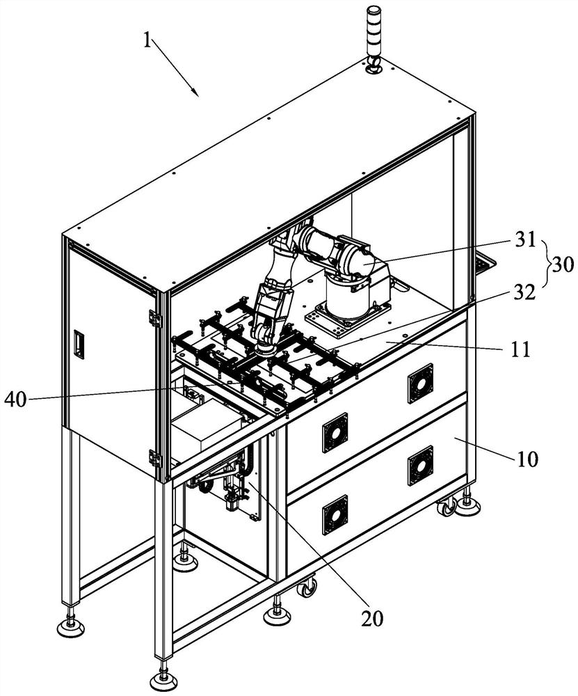
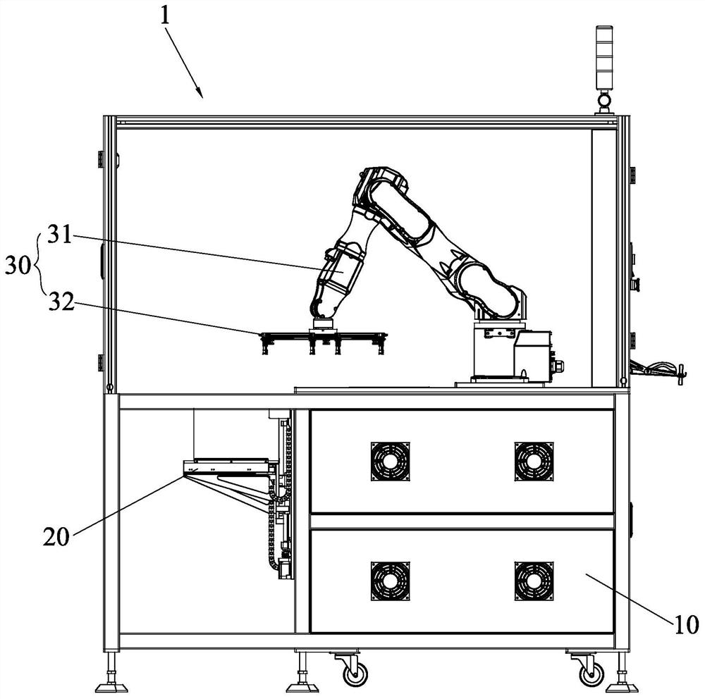
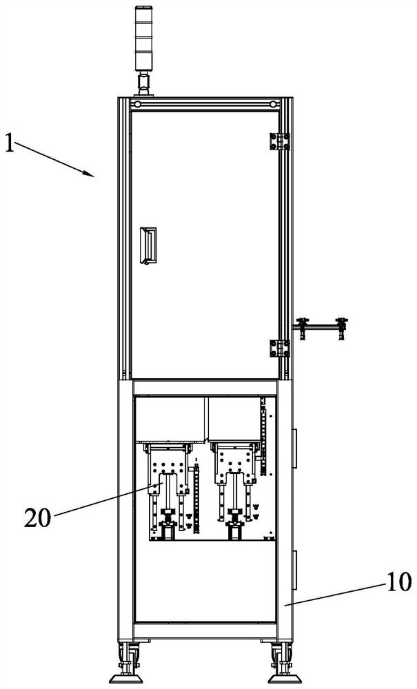
The invention discloses automatic feeding and discharging equipment and an automatic feeding and discharging method. The equipment comprises a rack, a feeding and discharging mechanism and a material moving mechanism, wherein the feeding and discharging mechanism and the material moving mechanism are arranged on the rack; the feeding and discharging mechanism comprises a feeding assembly and a discharging assembly; the feeding assembly and the discharging assembly are arranged on a mechanism mounting plate side by side; the feeding assembly comprises a Y-axis linear module, a Y-axis linear guide rail and a lifting bracket; the Y-axis linear module can drive a lifting bracket to reciprocate along the Y-axis linear guide rail; the discharging assembly and the feeding assembly are the same in structure; and the material moving mechanism comprises a robot and a material suction jig connected with the robot. By adopting the automatic feeding and discharging equipment disclosed by the invention, automatic feeding and discharging can be achieved; manual operation is replaced; intelligent manufacturing is achieved; production efficiency is improved; one person can operate a plurality of devices, so manpower investment is reduced; in addition, the equipment runs stably; and product quality is effectively guaranteed.

Description

technical field [0001] The invention relates to the technical field of automation equipment, in particular to an automatic loading and unloading equipment and an automatic loading and unloading method. Background technique [0002] With the technological development of intelligent manufacturing and the needs of industrial upgrading, manual operation is developing to semi-automatic equipment, and semi-automatic equipment is developing to fully-automatic equipment. However, early manufacturing companies have purchased multiple semi-automatic equipment, and one person operates one semi-automatic equipment. , It takes more manpower, manual operation is labor-intensive, prone to fatigue, production efficiency and product quality are unstable. In order to reduce capital investment and make full use of existing semi-automated equipment resources for industrial upgrading to realize intelligent manufacturing, there is an urgent need for an automatic loading and unloading equipment to...

Claims


Application Information

Patent Timeline
Patent Type & Authority Applications(China)
IPC IPC(8): B65G47/91B65G43/08
CPCB65G43/08B65G47/914
Inventor 陈妙芳赵继伟
Owner XIAMEN HONGXIN ELECTRON TECH
Why Eureka
Try Eureka