Cloth bag seal sewing machine

A technology for sewing machines and cloth bags, which is applied to pocket sewing machines, sewing machine components, needle holders for sewing machines, etc., can solve problems such as affecting the shape, and achieve the effects of preventing expansion, preventing excessive sliding and pulling, and increasing friction.

Inactive Publication Date: 2021-05-14
陈娅雄
View PDF10 Cites 0 Cited by
  • Summary
  • Abstract
  • Description
  • Claims
  • Application Information

AI Technical Summary

Problems solved by technology

[0004] When the thread body of the cloth bag has a certain degree of elasticity, when the inclined plane moves into the sewing opening, the lines will be pulled apart by the gravity hanging from the lower end, and the number of stitches in the seam will be different, which will affect the overall shape after forming form

Method used


Image

  • Cloth bag seal sewing machine
  • Cloth bag seal sewing machine
  • Cloth bag seal sewing machine

Examples


Embodiment 1

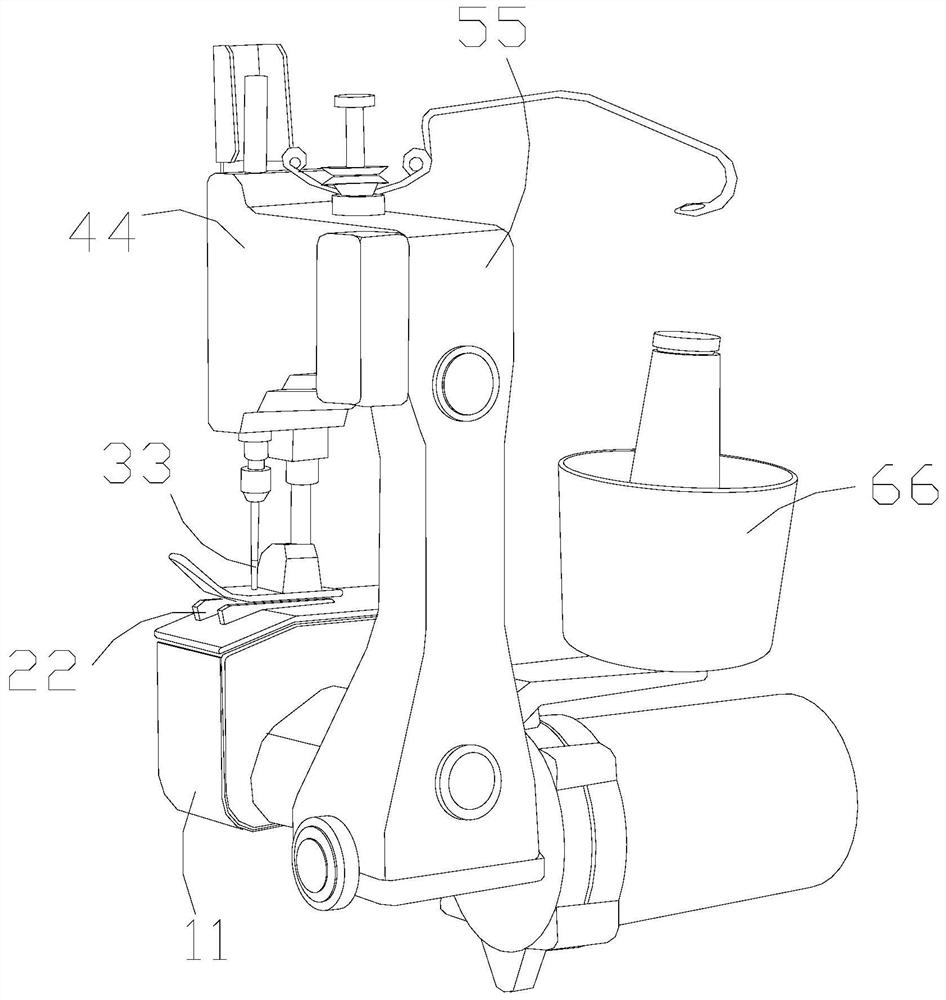
[0032] as attached figure 1 to attach Image 6 Shown:

[0033] The present invention provides a cloth bag sealing sewing machine, the structure of which includes a spacer bottom 11, a bracket 22, a sewing head 33, an impact box 44, a support frame 55, and a thread barrel 66, and the lower surface of the bracket 22 is welded to the spacer bottom 11. On the upper surface, the sewing head 33 is installed inside the lower end of the impact box 44 , the impact box 44 is welded to the outer surface of the support frame 55 , and the thread barrel 66 is located at the side of the support frame 55 .

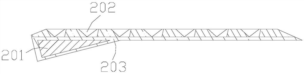
[0034] The bracket 22 includes a support block 201 , a socket 202 , and a partition 203 , the support block 201 is embedded in the partition 203 , and the socket 202 is installed on the upper surface of the partition 203 .

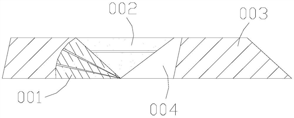
[0035] Wherein, the bracket 202 includes a fan 001, a corner 002, a spacer 003, and an opening 004. The fan 001 is attached to the outer surface of the corner 002, ...

Embodiment 2

[0042] as attached Figure 7 to attach Figure 9 Shown:

[0043]Wherein, the sewing head 33 includes an abutment angle 301, a moving block 302, a needle body 303, and a spring 304. The abutment angle 301 and the moving block 302 are an integral structure, and the spring 304 is embedded in the inside of the needle body 303. The lower part of the spring 304 is connected with the moving block 302, and the abutting angle 301 is distributed around the outside of the needle body 303, and the moving block 302 is connected between the force-bearing part and the fixed part to play the role of a central drive, and the abutting angle 301 is in contact with foreign objects, and it is pressed and fixed.

[0044] Wherein, the abutment angle 301 includes a pressing head m01 and a hard angle m02, the outer surface of the hard angle m02 is connected with the pressing head m01, the hard angle m02 has a triangular structure, and the pressing head m01 is connected with the foreign object The c...


PUM


Abstract

The invention discloses a cloth bag seal sewing machine which structurally comprises a partition bottom, a bracket, a sewing head, an impact box, a supporting frame and a bobbin, wherein the lower surface of the bracket is welded to the upper surface of the partition bottom, the sewing head is installed in the lower end of the impact box, the impact box is welded to the outer surface of the supporting frame, the impact box is continuously pushed to the lower side of the sewing head through external force, thus allowing the sewing head to seal a cloth bag, a spreading fan of the sewing head can support the range of a rubber corner, when the rubber corner is subjected to reverse force of cloth, an external object is supported and attached, when the cloth is pulled by sagging force, the cloth can be fixed in a counter-force mode, excessive sliding and pulling of the cloth are prevented, when a needle body moves downwards, an abutting corner moves downwards along with the needle body, the abutting corner can abut against the surface of the cloth bag to extrude the spring through a moving block, a pressing and fixing head makes contact with the cloth bag and a foreign object, and pressing and fixing are performed according to deformation of the foreign object, so that when the needle body penetrates through the cloth bag, the periphery of the cloth bag can be pressed and fixed in a sealing process of the cloth bag, and expansion of the cloth bag is prevented.

Description

technical field [0001] The invention belongs to the field of sewing machines, and more specifically relates to a cloth bag sealing sewing machine. Background technique [0002] When the cloth bag needs to be sealed, the personnel will move it into the sewing machine one by one for operation, and the sewing table will have a certain inclination angle, in order to assist the cloth not to pile up together, so that it can be moved into the sewing mouth for operation. [0003] Based on the above-mentioned inventor's discovery, the existing cloth bag sealing sewing machine mainly has the following deficiencies, such as: [0004] When the thread body of the cloth bag has a certain degree of elasticity, when the inclined plane moves into the sewing opening, the lines will be pulled apart by the gravity hanging from the lower end, and the number of stitches in the seam will be different, which will affect the overall shape after forming form. [0005] Therefore need to propose a ki...

Claims


Application Information

Patent Timeline
IPC IPC(8): D05B13/00D05B55/00D05B35/00
CPCD05B13/00D05B55/00D05B35/00
Inventor 张玉妹
Owner 陈娅雄
Why Eureka
Try Eureka