
Rolling bearing fault diagnosis method and system

A rolling bearing and fault diagnosis technology, applied in the testing of machine/structural components, testing of mechanical components, instruments, etc., can solve the problem of less adaptive selection method of penalty factor α and so on

Active Publication Date: 2021-05-14
SHANDONG UNIV
View PDF13 Cites 5 Cited by
  • Summary
  • Abstract
  • Description
  • Claims
  • Application Information

AI Technical Summary

Problems solved by technology

However, there are relatively few adaptive selection methods for the penalty factor α

Method used


Image

  • Rolling bearing fault diagnosis method and system
  • Rolling bearing fault diagnosis method and system
  • Rolling bearing fault diagnosis method and system

Examples


Embodiment 1

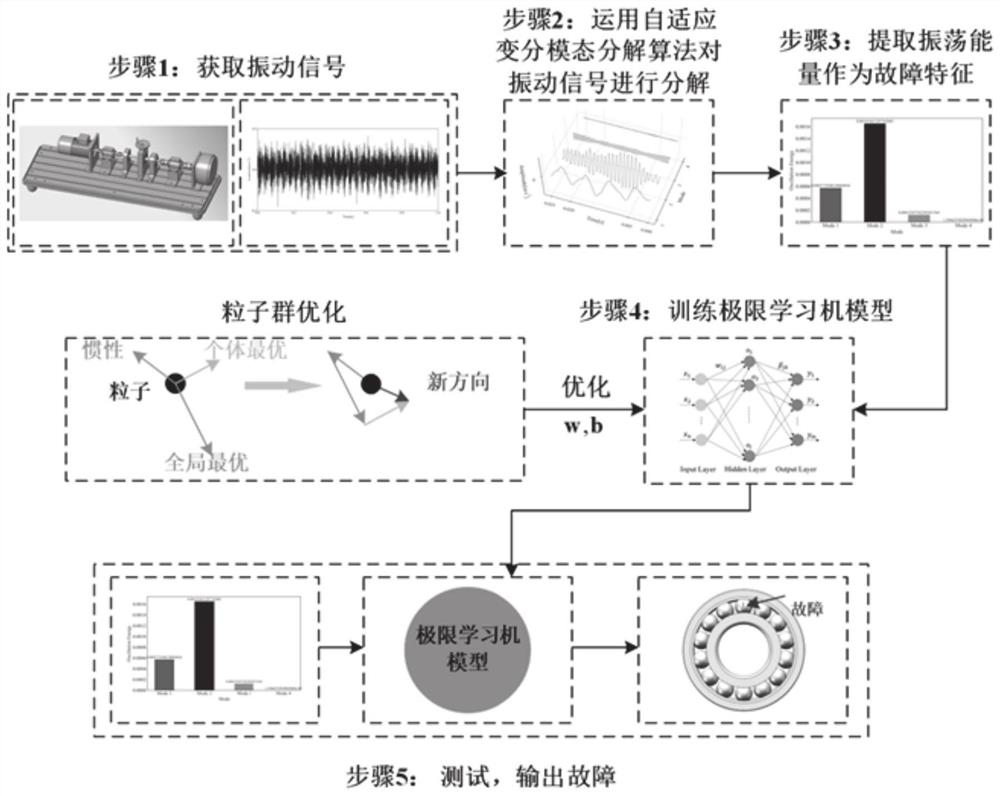
[0033] The present disclosure provides a rolling bearing fault diagnosis method, including:

[0034] Collect the vibration signal of the rolling bearing to be detected, and randomly divide the training set and the test set;

[0035] Input the vibration signal of the rolling bearing into the fault diagnosis model to obtain the fault diagnosis result;

[0036] The fault diagnosis model is obtained by forming a training set and a test set based on time-domain vibration signals of different fault types of rolling bearings for training and testing. The step of establishing the fault diagnosis model includes adaptively adapting the time-domain vibration signals of each fault type in the training set. The variational modal decomposition obtains the corresponding modal components, obtains the fault characteristics of each modal component, and uses the fault characteristics as the input of the classifier model; the penalty factor of the adaptive variational modal decomposition is deter...

Embodiment 2

[0059] The present disclosure provides a rolling bearing fault diagnosis system, including:

[0060] The data acquisition module is configured to: collect the vibration signal of the rolling bearing to be detected;

[0061] The fault diagnosis module is configured to: input the vibration signal of the rolling bearing into the fault diagnosis model to obtain the fault diagnosis result;

[0062] The fault diagnosis model is obtained by forming a training set and a test set based on time-domain vibration signals of different fault types of rolling bearings for training and testing. The step of establishing the fault diagnosis model includes adaptively adapting the time-domain vibration signals of each fault type in the training set. The variational modal decomposition obtains the corresponding modal components, obtains the fault characteristics of each modal component, and uses the fault characteristics as the input of the classifier model; the penalty factor of the adaptive vari...

Embodiment 3

[0065] A computer-readable storage medium is used for storing computer instructions. When the computer instructions are executed by a processor, the method for diagnosing rolling bearing faults as described in the above-mentioned embodiments is completed.


PUM


Abstract

The invention provides a rolling bearing fault diagnosis method and system. The rolling bearing fault diagnosis method comprises the steps following steps of: collecting a vibration signal of a to-be-detected rolling bearing; and inputting the rolling bearing vibration signal into a fault diagnosis model to obtain a fault diagnosis result. The fault diagnosis model is obtained by training and testing a training set and a test set which are formed based on time domain vibration signals of different fault types of rolling bearings The establishment process of the fault diagnosis model comprises the following steps of: performing adaptive variational mode decomposition on the time domain vibration signals of each fault type in the training set to obtain corresponding mode components; and obtaining fault features of each modal component, and taking the fault features as input of a classifier model. The penalty factor of the self-adaptive variational mode decomposition is determined according to the cross correlation degree of frequency spectra, and therefore, aliasing among all modal components is effectively avoided, fault feature information of the vibration signals can be reserved to the maximum extent, and the model can have good generalization performance.

Description

technical field [0001] The present disclosure relates to the field of rolling bearing fault diagnosis, in particular to a rolling bearing diagnosis method and system based on AVMD and AWPSO-ELM. Background technique [0002] The statements in this section merely provide background information related to the present disclosure and may not necessarily constitute prior art. [0003] With the further development of industrialization, more and more rotating machinery is applied to industrial scenes. Rolling bearings, as a typical device of rotating machinery, are the core basic components clearly listed in the "package" breakthrough action in the key areas of the national "Guidelines for the Implementation of Industrial Strong Foundation Project (2016-2020)", and play an extremely important role in rotating devices. role. The running state of rolling bearings affects the normal operation of mechanical equipment. If the bearings run in an abnormal state, it may cause irreparable...

Claims


Application Information

Patent Timeline
IPC IPC(8): G01M13/045
CPCG01M13/045
Inventor 张法业王金喜姜明顺张雷隋青美贾磊
Owner SHANDONG UNIV
Learn More