Antenna near-field measurement method and device using interpolation algorithm

A measurement method and interpolation algorithm technology, applied in the direction of measurement devices, antenna radiation patterns, and measurement of electrical variables, can solve problems such as unsatisfactory interpolation results, affecting accuracy, and increasing the amount of calculation, so as to improve measurement efficiency, reduce requirements, The effect of reducing the number

Active Publication Date: 2021-05-14
上海莱天通信技术有限公司
View PDF19 Cites 6 Cited by
  • Summary
  • Abstract
  • Description
  • Claims
  • Application Information

AI Technical Summary

Problems solved by technology

This method still has some shortcomings
First, the near-field electric field components directly obtained in the measurement system are usually amplitude and phase values. This method requires a mathematical transformation to convert the amplitude and phase components into real and imaginary components, which increases the amount of additional calculations.
Second, this method only has a small interpolation error when the scanning surface (also called the sampling surface) is spherical. After changing the shape of the scanning surface, the interpolation result of the imaginary component of the electric field is not ideal, which affects the accuracy of subsequent calculations
Third, if the method is changed to interpolation of the amplitude and phase components of the near-field electric field, the curve obtained by bilinear interpolation is not a smooth curve because the amplitude value of the electric field is very gentle compared with the phase value. The interpolation results do not fit well with the theoretical results at locations where the values ​​change abruptly

Method used


Image

  • Antenna near-field measurement method and device using interpolation algorithm
  • Antenna near-field measurement method and device using interpolation algorithm
  • Antenna near-field measurement method and device using interpolation algorithm

Examples


Embodiment Construction

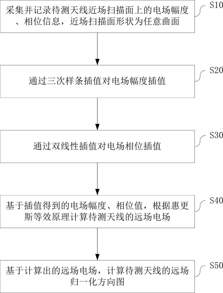
[0031] see figure 1 , the antenna near-field measurement method using an interpolation algorithm proposed in this application includes the following steps.

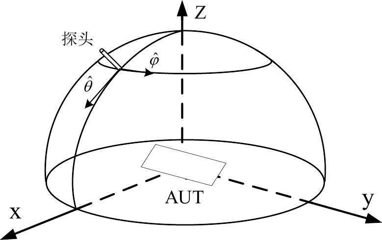
[0032] Step S10: collecting and recording the electric field amplitude and phase information on the near-field scanning surface of the antenna under test. The near-field scanning surface is in any curved shape and must satisfy the following three conditions at the same time.

[0033] Condition 1: The near-field scanning surface must be located in a space where the electromagnetic field is not zeroed.

[0034] Condition 2: The near-field scanning surface must be located in the radiation near-field area of ​​the antenna under test, and the distance from the antenna under test is greater than and less than 2D 2 / λ. Wherein, D represents the maximum size of the antenna under test, and λ represents the wavelength of the central operating frequency of the antenna under test. Preferably, the near-field scanning surface is ...


PUM


Abstract

The invention discloses an antenna near-field measurement method using an interpolation algorithm. The method comprises the steps: S10, collecting and recording electric field amplitude and phase information on a near-field scanning surface of the antenna to be measured, wherein the near-field scanning surface is in any curved surface shape and needs to meet the following three conditions at the same time. S20, interpolating the electric field amplitude on the near-field scanning surface of the antenna to be measured through cubic spline interpolation. S30, interpolating the electric field phase on the near-field scanning surface of the antenna to be measured through bilinear interpolation. S40, calculating a far-field electric field of the to-be-tested antenna according to a Huygens equivalence principle based on the near-field electric field amplitude and phase value of the to-be-tested antenna obtained by interpolation. and S50, based on the calculated far-field electric field of the to-be-tested antenna, calculating a far-field normalized directional diagram of the to-be-tested antenna. The near-field scanning surface in the method is not limited to a plane, a cylindrical surface and a spherical surface, and can be changed into any curved surface according to the actual measurement environment change.

Description

technical field [0001] The present application relates to an antenna near field measurement method, in particular to an antenna near field measurement method using an interpolation algorithm. Background technique [0002] Antenna measurement methods mainly include direct method and indirect method. The direct method is the far-field measurement method, and the indirect method is the near-field measurement method. Antenna near-field measurement is generally carried out in a microwave anechoic chamber. The probe antenna is used to scan to obtain the data of the radiation field in the near-field area of ​​the antenna to be tested, and the far-field pattern of the antenna is calculated through near-far field transformation. [0003] According to different types of scanning surfaces, common antenna near-field measurements include planar, spherical, and cylindrical near-field measurements. With the increasing application of conformal antennas, it is difficult to form a regular sc...

Claims


Application Information

Patent Timeline
Patent Type & Authority Applications(China)
IPC IPC(8): G01R29/10G01R29/08
CPCG01R29/0871G01R29/0892G01R29/10
Inventor 周建华洪涛毛小莲王浩然姜文李吉龙
Owner 上海莱天通信技术有限公司
Why Eureka
Try Eureka