Double-rod type combined transformer rack

A transformer and rod type technology, which is applied in the direction of transformer/reactor installation/support/suspension, hoisting device, spring mechanism, etc., which can solve the problems of inconvenient installation and operation, low installation efficiency, and heavy weight

Active Publication Date: 2021-05-14
SHENYANG HAOCHENG FEICHI ELECTRIC
View PDF6 Cites 2 Cited by
  • Summary
  • Abstract
  • Description
  • Claims
  • Application Information

AI Technical Summary

Problems solved by technology

[0003] During installation, the two poles must be erected first, and at the corresponding installation position of each cross-arm, the hoop and cross-arm must be aligned with the installation position at the same time, and then fixed with screws. The process of fixing and connecting requires the cooperation of multiple people. , for the double-pole transformer stand, there are many cross-arms installed on the pole body. In order to realize the layout and installation of power transmission lines and insulators, it is necessary to install hoops, cross-arms, connecting plates and other structures on the top of the pole body and on the pole body. All accessories The installation must be done after the pole body is erected, and the installer climbs to the top of the pole for installation. The installation efficiency is low, and the installation accessories are metal parts, which are heavy and difficult to transport to high altitudes, which brings great inconvenience to the installation operation.

Method used


Image

  • Double-rod type combined transformer rack
  • Double-rod type combined transformer rack
  • Double-rod type combined transformer rack

Examples


Embodiment Construction

[0022] In order to make the object, technical solution and advantages of the present invention clearer, the present invention will be further described in detail below in combination with specific embodiments and with reference to the accompanying drawings. It should be understood that these descriptions are exemplary only, and are not intended to limit the scope of the present invention. Also, in the following description, descriptions of well-known structures and techniques are omitted to avoid unnecessarily obscuring the concept of the present invention.

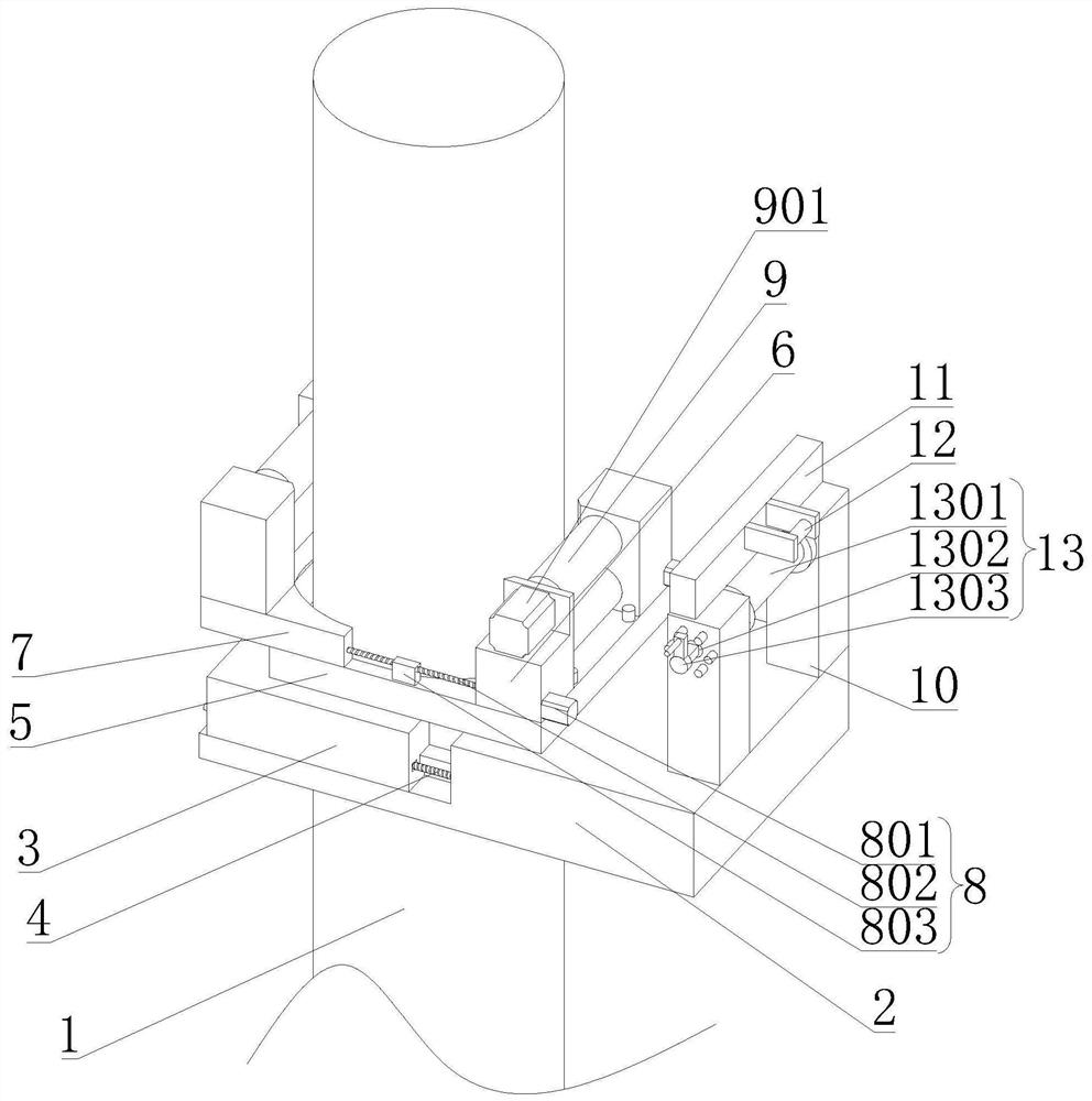
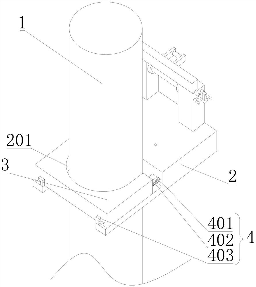
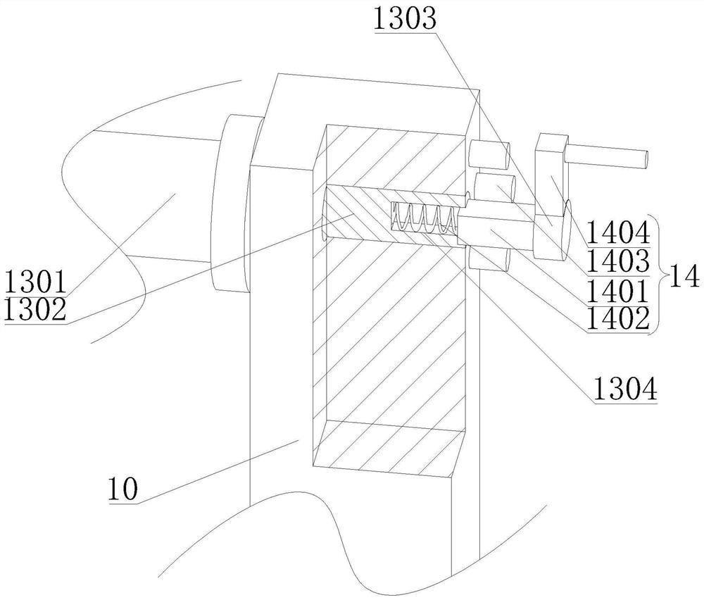
[0023] like Figure 1-3 As shown, the present invention proposes a double-rod combined transformer stand, including a utility pole 1, a mounting frame 2, a first clamping frame 3, a connecting frame 5, a mounting table 6, a second clamping frame 7, and rubber wheels 9. Support rod 10 and take-up mechanism 13;

[0024] The mounting frame 2, the first clamping frame 3, the connecting frame 5 and the second clamping frame ...


PUM


Abstract

A double-rod type combined transformer rack comprises a telegraph pole, a mounting frame, a first clamping frame, a connecting frame, a mounting table, a second clamping frame, a rubber wheel, a supporting rod and a take-up mechanism, wherein the first clamping frame is arranged on the mounting frame in a sliding manner; the telegraph pole is located between the first clamping frame and the mounting frame; a first locking mechanism for driving the first clamping frame to move is arranged on the mounting frame; the second clamping frame is arranged on the connecting frame in a sliding manner; the connecting frame is provided with a second locking mechanism used for driving the second clamping frame to move; the mounting table is arranged on the connecting frame and the second clamping frame, and the rubber wheel is rotationally arranged on the mounting table; a third motor for driving the rubber wheel to rotate is arranged on the mounting table; and the supporting rod is arranged on the mounting frame, and the take-up mechanism is arranged on the supporting rod. The third motor drives the rubber wheel to rotate, so that the mounting frame ascends, the mounting frame drives the supporting frame and the take-up mechanism to move, and mounting accessories are conveniently transported to the high altitude through the take-up mechanism.

Description

technical field [0001] The invention relates to the technical field of power supply equipment, in particular to a double-rod combined transformer stand. Background technique [0002] Transformer is a device that uses the principle of electromagnetic induction to change AC voltage. The main components are primary coil, secondary coil and iron core (magnetic core). The main functions are: voltage transformation, current transformation, impedance transformation, isolation, voltage stabilization (magnetic saturation transformer), etc. [0003] During installation, the two poles must be erected first, and at the corresponding installation position of each cross-arm, the hoop and cross-arm must be aligned with the installation position at the same time, and then fixed with screws. The process of fixing and connecting requires the cooperation of multiple people. , for the double-pole transformer stand, there are many cross-arms installed on the pole body. In order to realize the l...

Claims


Application Information

Patent Timeline
Patent Type & Authority Applications(China)
IPC IPC(8): H01F27/06B66D1/74
CPCH01F27/06B66D1/74Y02E10/50
Inventor 李家坤潘世一关振哲
Owner SHENYANG HAOCHENG FEICHI ELECTRIC
Why Eureka
Try Eureka