An electrostatic chuck device and glue remover

An electrostatic chuck and placement surface technology, which is applied in the manufacturing of circuits, electrical components, semiconductor/solid-state devices, etc., can solve the problems of small edge adsorption force and large electrostatic chuck adsorption force, and achieve atmospheric flow and uniform adsorption force. , the effect of large electrostatic adsorption force

Active Publication Date: 2021-06-29
宁波润华全芯微电子设备有限公司
View PDF14 Cites 0 Cited by
  • Summary
  • Abstract
  • Description
  • Claims
  • Application Information

AI Technical Summary

Problems solved by technology

[0003] Therefore, the embodiment of the present invention provides an electrostatic chuck device, which solves the problem that the middle adsorption force of the electrostatic chuck is large and the edge adsorption force is small

Method used


Image

  • An electrostatic chuck device and glue remover
  • An electrostatic chuck device and glue remover
  • An electrostatic chuck device and glue remover

Examples


no. 1 example

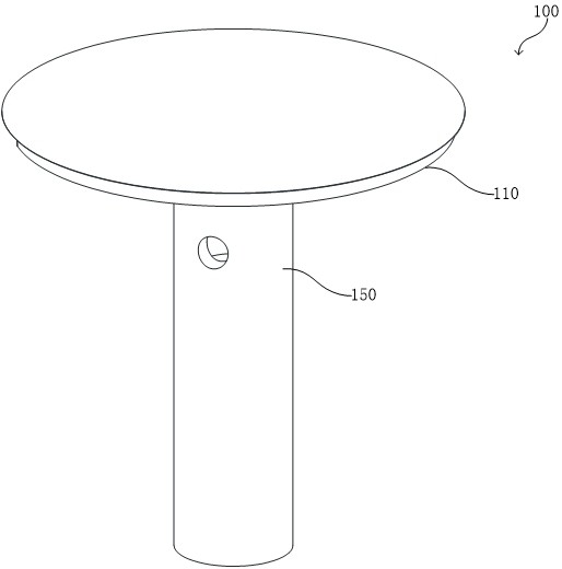
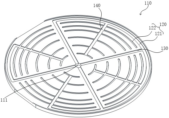
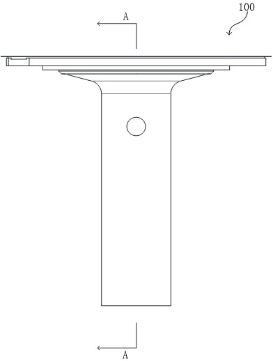
[0037] see figure 1 , which is a schematic structural view of the electrostatic chuck device 100 provided in the first embodiment of the present invention, including: an electrostatic chuck 110 . combine figure 2 , the electrostatic chuck 110 is provided with a placement surface, and a plurality of circumferential air passages 120 , a plurality of radial air passages 130 and a plurality of return air passages 140 are arranged on the placement surface. Among them, a plurality of circumferential air passages 120 form a concentric multi-layer structure in the radial direction; a plurality of radial air passages 130 communicate with the air hole 111 in the center of the placement surface and the outermost circumferential air passage 120, and communicate with the remaining circumferential air passages. The air passage 120 is blocked; there are multiple return air passages 140 , and each return air passage 140 communicates with all the circumferential air passages 120 between any ...

no. 2 example

[0071] The second embodiment of the present invention provides a glue remover (not shown in the figure), including the electrostatic chuck device 100 provided in the first embodiment. Wherein, the electrostatic chuck device 100 can be used for fixing the wafer during the process of wafer degluing by the degumming machine, for example, installed in the degumming cavity.

[0072] Preferably, the degumming machine is a fully automatic degumming machine or a semi-automatic degumming machine.


PUM


Abstract

The invention discloses an electrostatic chuck device and a degumming machine. An electrostatic chuck device is characterized in that: an electrostatic chuck is provided with a placement surface, and the placement surface includes: a plurality of circumferential air passages , forming a concentric multi-layer structure along the radial direction; a plurality of radial air passages, which communicate with the air hole in the center of the placement surface and the peripheral air passage in the outermost layer, and are blocked from the rest of the peripheral air passages; a plurality of return air passages, each of the return air passages communicates with all the circumferential air passages between any two adjacent radial air passages, and each of the return air passages faces one end of the air hole It communicates with the innermost circumferential air passage, and is blocked from the air hole; wherein, the air flow is blown out from the air hole and flows to the outermost circumferential air passage along the plurality of radial air passages, and then flows to the outermost circumferential air passage. It flows to the return air passage, and then flows to the circumferential air passages on both sides of the return air passage. The invention solves the problems of large adsorption force in the middle and small adsorption force of the edge of the electrostatic chuck.

Description

technical field [0001] The invention relates to the field of wafers in the semiconductor industry, in particular to an electrostatic chuck device and a glue remover. Background technique [0002] At present, in the wafer manufacturing process, precise and stable positioning of the wafer is required. Existing wafer fixing devices often use electrostatic chucks to adsorb wafers. The electrostatic chucks use multiple concentric circular gas paths and multiple radial gas paths to connect each of the circular gas paths. After gas is fed into the electrostatic chuck, the central circular gas path is filled with gas first, and the outer circular gas path will have gas flow after it, thus resulting in the gas in the outer circular gas path The flow rate is smaller than that of the circular gas path inside, so that the adsorption force on the outside of the electrostatic chuck is also smaller than that of the center. Contents of the invention [0003] Therefore, the embodiment of...

Claims


Application Information

Patent Timeline
Patent Type & Authority Patents(China)
IPC IPC(8): H01L21/683H01L21/67
CPCH01L21/67126H01L21/6833H01L21/6838
Inventor 王冲傅立超
Owner 宁波润华全芯微电子设备有限公司
Why Eureka
Try Eureka