
Base station antenna with same-frequency mutual coupling effect reducing device

A base station antenna and effect technology, which is applied in the direction of antenna, antenna coupling, antenna array, etc., can solve the problems affecting the strength and directionality of the system radiation field, the deflection of the main beam of the system pattern, and the poor effect of mutual coupling effect elimination.

Pending Publication Date: 2021-05-14
HUIZHOU SPEED WIRELESS TECH CO LTD
View PDF0 Cites 4 Cited by
  • Summary
  • Abstract
  • Description
  • Claims
  • Application Information

AI Technical Summary

Problems solved by technology

This method is effective when there is a large distance between two columns of antennas with different frequencies (the distance between two columns of antennas is greater than 1 / 4 of the antenna center frequency wavelength). However, in the pursuit of miniaturization of base stations, adjacent The distance between the two columns of antennas is gradually compressed, often less than 1 / 4 of the wavelength of the antenna center frequency. If the main beam is deflected, the pattern of the antennas on both sides of the reflector will be distorted to a certain extent, thus affecting the strength and directivity of the radiation field of the system.

Method used


Image

  • Base station antenna with same-frequency mutual coupling effect reducing device
  • Base station antenna with same-frequency mutual coupling effect reducing device
  • Base station antenna with same-frequency mutual coupling effect reducing device

Examples


Embodiment Construction

[0031] The embodiments will be described in detail hereinafter, examples of which are illustrated in the accompanying drawings. When the following description refers to the accompanying drawings, the same numerals in different drawings refer to the same or similar elements unless otherwise indicated. The implementations described in the following examples do not represent all implementations consistent with this application. These are merely examples of systems and methods consistent with aspects of the present application as recited in the claims.

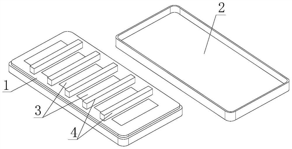
[0032] see figure 1 , is a schematic diagram of the overall structure of a base station antenna equipped with a same-frequency mutual coupling effect reduction device provided in an embodiment of the present application.

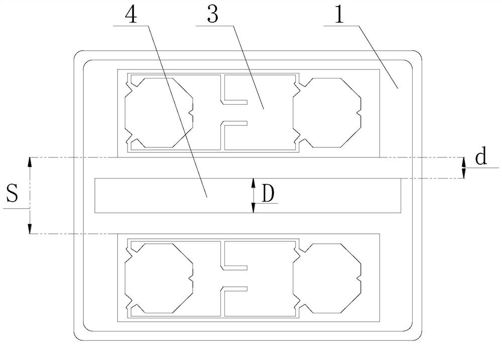
[0033] see figure 2 , is a structural schematic diagram of an antenna unit and a decoupling device of a base station antenna equipped with a device for reducing the same-frequency mutual coupling effect prov...


PUM

PropertyMeasurementUnit
Frequencyaaaaaaaaaa
Widthaaaaaaaaaa
Heightaaaaaaaaaa

Abstract

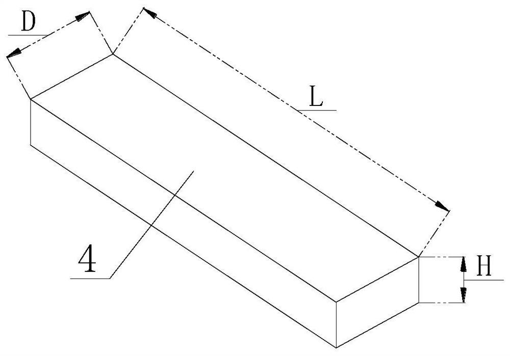
The invention provides a base station antenna with a same-frequency mutual coupling effect reducing device, which comprises a metal base, an outer cover, a plurality of columns of antenna units and decoupling devices, and is characterized in that the decoupling devices are arranged between two adjacent columns of antenna units; the frequencies of the multiple columns of antenna units are the same, and the distance S between every two adjacent columns of antenna units is smaller than 1 / 4 of the center frequency wavelength of the antenna units and larger than 1 / 10 of the center frequency wavelength of the antenna units; the length L of the decoupling device is greater than the length of the antenna unit, the height H is equal to the height of the antenna unit, and the width D is greater than 1 / 16 of the central frequency wavelength of the antenna unit. The base station can be provided with more antennas by reducing the distance between the multiple columns of antenna units so as to enlarge the communication capacity of the base station, and the decoupling device is arranged between the two adjacent columns of antenna units so as to reduce the mutual coupling effect between the adjacent antenna units, so that the mutual coupling effect between the antenna units is effectively reduced under the condition that the design size of the base station antenna is met.

Description

technical field [0001] The present application relates to the technical field of mobile communication, and in particular to a base station antenna equipped with a same-frequency mutual coupling effect reducing device. Background technique [0002] In order to adapt to the development of mobile communication technology, especially the continuous development of the fifth generation mobile communication based on massive MIMO (Multiple-Input Multiple-Output) technology, the number of antennas (including antennas in mobile terminals or base stations) presents Doubling trend. [0003] Research shows that the capacity of the communication system increases linearly with the increase of the number of antennas when the output power is constant, the signal-to-noise ratio is constant, and the antenna elements are not correlated with each other. Therefore, the greater the number of antennas installed in the same base station, the greater the communication capacity. However, the large-s...

Claims


Application Information

Patent Timeline
IPC IPC(8): H01Q1/24H01Q1/36H01Q1/42H01Q1/52H01Q21/00
CPCH01Q1/246H01Q1/36H01Q1/42H01Q1/523H01Q21/00
Inventor 汤小俊张凯
Owner HUIZHOU SPEED WIRELESS TECH CO LTD
Learn More