Method and device for eliminating intercoupling effect at transmitter side

A transmitter-side and transmitter technology, applied in the field of multiple-input multiple-output wireless communication systems, can solve the problem of eliminating the mutual coupling effect of the MIMO system, which is not proposed, and achieve the effect of eliminating the mutual coupling effect and improving the system capacity.

Inactive Publication Date: 2012-05-09
ALCATEL LUCENT SHANGHAI BELL CO LTD
View PDF2 Cites 3 Cited by
  • Summary
  • Abstract
  • Description
  • Claims
  • Application Information

AI Technical Summary

Problems solved by technology

No solution to eliminate mutual coupling effects in MIMO systems has been proposed in the prior art

Method used


Image

  • Method and device for eliminating intercoupling effect at transmitter side
  • Method and device for eliminating intercoupling effect at transmitter side
  • Method and device for eliminating intercoupling effect at transmitter side

Examples


Embodiment Construction

[0018] System model:

[0019] The system model considering the mutual coupling effect of the transmitter and the receiver can be expressed as: (1)

[0020] y=C r HC t x+z(1)

[0021] where x is the transmitted signal vector, C r is the coupling matrix at the receiver, C t is the coupling matrix at the transmitter, H is the spatial channel matrix, and z is the additive noise vector.

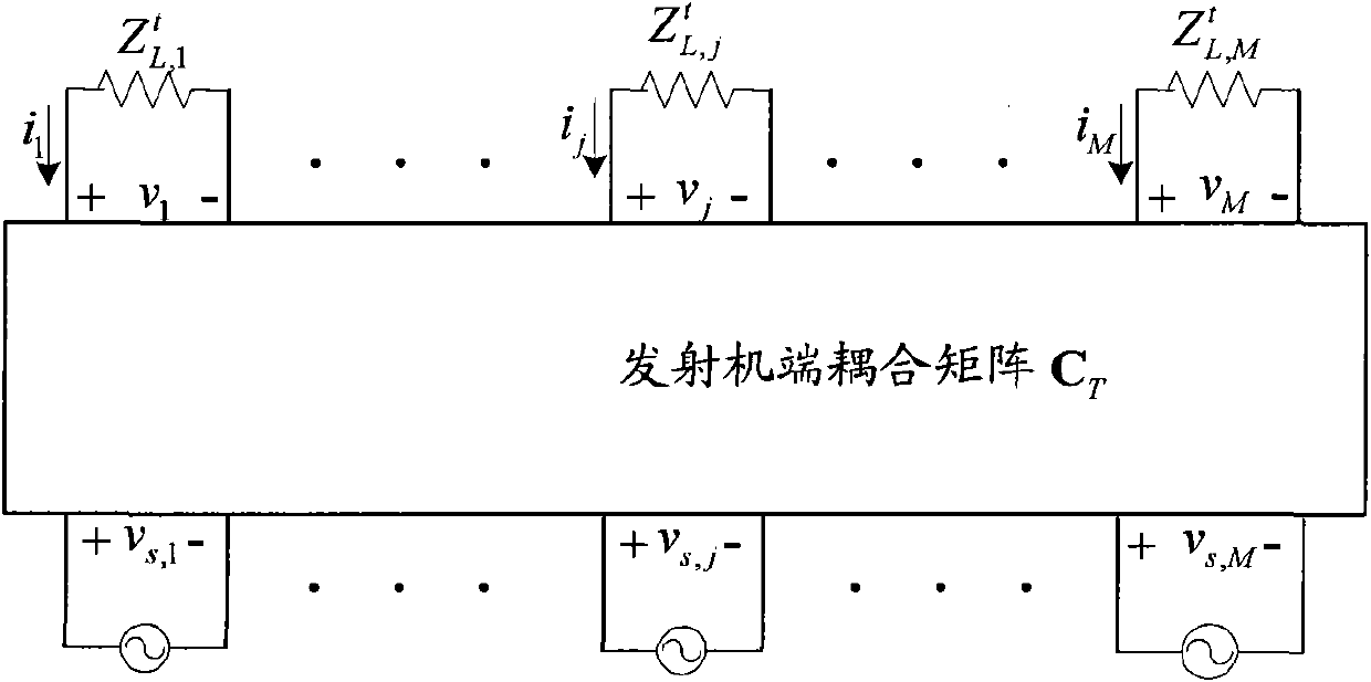
[0022] The antenna array at the transmitter can be expressed as figure 1 The circuit network shown.

[0023] According to Kirchoff's voltage law (KVL), it can be concluded that:

[0024] C t = Z L t ( Z t + Z L t ) - 1 - - - ( ...


PUM


Abstract

The invention provides a method and device for eliminating an intercoupling effect at a transmitter side, which solves the problem that the system capacity is lowered arising from the intercoupling among antenna units in the prior art. A transmitter acquires a coupling matrix at the transmitter side, carries out pretreatment on a signal to be transmitted according to the coupling matrix so as to generate a decoupled signal, and then, transmits the decoupled signal to a receiver. When the transmitter also carries out a decoupling operation on an original training sequence like that on the signal to be transmitted, improvement is not needed to carry out at a receiver side; and when the transmitter transmits the original training sequence which is not decoupled, the receiver further needs to carry out backward processing of a decoupling operation on the received signal so as to reconstruct the original signal. With the adoption of the technical scheme provided by the invention, the system capacity can be increased.

Description

technical field [0001] The invention relates to a multiple-input multiple-output wireless communication system, in particular to a method and device for eliminating the mutual coupling effect at the transmitter end. Background technique [0002] As we all know, in a multi-input multi-output (Multi-Input Multi-Output) system, theoretically increasing the number of antennas can improve system performance. However, in practical applications, the size of the antenna array is limited by space. For a fixed size antenna array, increasing the number of antennas will decrease the distance between antenna elements. When the distance between the antenna elements is arranged very close, if the mutual coupling effect between the antenna elements is not considered in advance in the system design, the performance of the system will be greatly reduced. [0003] The so-called mutual coupling between the antenna elements refers to the mutual interaction between the various antenna elements....

Claims


Application Information

Patent Timeline
Patent Type & Authority Applications(China)
IPC IPC(8): H04B7/08H04B7/06H04L1/06H04L25/03H04L25/02
Inventor 陈晋辉吴克颖蔡立羽
Owner ALCATEL LUCENT SHANGHAI BELL CO LTD
Why Eureka
Try Eureka