Three-dimensional non-orthogonal tracking and scanning test head calibrating method

A technology of scanning probe and calibration method, which is applied in the direction of measuring devices, instruments, etc., can solve the problems of not being able to reflect the working conditions of the internal sensors of the three-dimensional non-orthogonal tracking scanning probe, adverse effects on accuracy, and large calibration errors.

Active Publication Date: 2018-09-28
SICHUAN UNIV
View PDF4 Cites 5 Cited by
  • Summary
  • Abstract
  • Description
  • Claims
  • Application Information

AI Technical Summary

Problems solved by technology

In the non-orthogonal structure of the three-dimensional tracking scanning probe, the mutual coupling effect is relatively serious, that is, the mutual coupling between the sensors inside the probe has an adverse effect on the accuracy
These factors cause the above calibration algorithm to fail to reflect the actual working conditions of the internal sensors of the 3D non-orthogonal tracking scanning probe, resulting in large calibration errors

Method used


Image

  • Three-dimensional non-orthogonal tracking and scanning test head calibrating method
  • Three-dimensional non-orthogonal tracking and scanning test head calibrating method
  • Three-dimensional non-orthogonal tracking and scanning test head calibrating method

Examples


Embodiment Construction

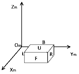
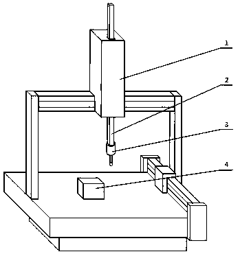
[0033] Step 1 Install the standard measuring cube Q ,Such as figure 1 shown, and operate a CMM using a variety of methods such as a calibrated touch probe or optical scanning to ensure its left L with front surface F machine coordinate axis , machine tool coordinate axis parallel, and read out its mounting coordinates, including: its front surface F , back surface B Corresponding machine coordinate axis coordinate value , left side L , right side R Corresponding machine coordinate axis coordinate value , on top U Corresponding machine coordinate axis Axis coordinate value . CMM C Install a three-dimensional non-orthogonal tracking scanning probe on the z-axis P (hereinafter referred to as the probe P ),Such as figure 2 shown.

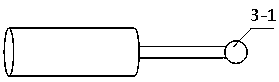
[0034] Step 2 Jog to control the three-coordinate measuring machine C drive probe P move so that the probe P ball finger I (Such as image 3 shown) with standard measuring cubes Q the front surface of F contact, such ...


PUM


Abstract

The invention discloses a three-dimensional non-orthogonal tracking and scanning test head calibrating method, and belongs to the field of precise instrument measurement. The three-dimensional non-orthogonal tracking and scanning test head calibrating method is designed for a coordinate measuring machine, a precise numerical control machine tool and other precise measuring instrument on the basisof a three-dimensional coordinate measuring system. By means of the method, through the coupling effect of a cubic-term fitting decoupling sensor, in cooperation with a corresponding data collecting method, by introducing a self-adaptive genetic algorithm for solution, the calibrating precision is greatly improved, and meanwhile external parameters and internal parameters of a test head are calibrated and the calibrating operation process is simplified. The method is suitable for the three-dimensional non-orthogonal tracking and scanning test head.

Description

technical field [0001] The invention belongs to the field of precision testing technology, instruments and precision machinery, in particular to a three-dimensional non-orthogonal tracking scanning probe calibration method based on a coordinate measuring machine. Background technique [0002] In manufacturing and processing, accurate and timely acquisition of characteristic information of the measured object can improve processing accuracy, improve part manufacturing efficiency, and reduce production costs. Measurement technology has become an important technology in the industrial field. At present, the detection methods of parts in the industrial field can be divided into two categories: contact and non-contact. Non-contact measurement such as laser measurement, structured light vision measurement, etc., has a high efficiency of information acquisition, and the accuracy is better in the laboratory environment, but in actual use, its measurement accuracy and stability are v...

Claims


Application Information

Patent Timeline
Patent Type & Authority Applications(China)
IPC IPC(8): G01B21/04
CPCG01B21/042
Inventor 于泽源万浩赵武陶冶郭鑫陈领于淼吴年汉廖莹胡晓李琴
Owner SICHUAN UNIV
Why Eureka
Try Eureka