
Vertical wire clamp

A technology of vertical wire and insulating tension wire clamp, applied in the field of vertical wire clamp, can solve the problems of convenience of use, adverse effect of device use effect, cumbersome cable clamping and installation, etc., and achieve the effect of convenient adjustment and convenient use.

Active Publication Date: 2021-05-14
ZHONGWANG ELECTRIC POWER TECH CO LTD
View PDF7 Cites 0 Cited by
  • Summary
  • Abstract
  • Description
  • Claims
  • Application Information

AI Technical Summary

Problems solved by technology

[0002] Wire clips are iron or aluminum metal accessories that can be fixed on the cable. Most of them need to bear a large pulling force during operation, and some also need to ensure good electrical contact at the same time. However, most devices in the prior art are fixed by The length of the connecting rod is installed and set, so that the device needs to be replaced with different lengths of connecting rods according to the actual use, which affects the convenience of the actual use of the equipment to a certain extent. Effects are somewhat adversely affected by

Method used


Image

  • Vertical wire clamp
  • Vertical wire clamp
  • Vertical wire clamp

Examples


Embodiment Construction

[0024] The following will clearly and completely describe the technical solutions in the embodiments of the present invention with reference to the accompanying drawings in the embodiments of the present invention. Obviously, the described embodiments are only some, not all, embodiments of the present invention.

[0025] Examples of the described embodiments are shown in the drawings, wherein like or similar reference numerals designate like or similar elements or elements having the same or similar functions throughout. The embodiments described below by referring to the figures are exemplary and are intended to explain the present invention and should not be construed as limiting the present invention.

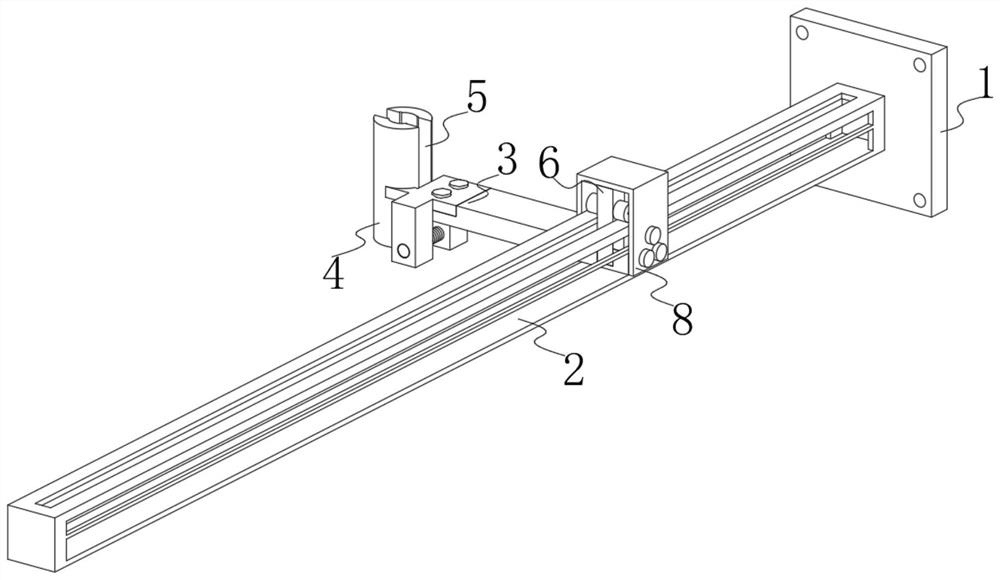
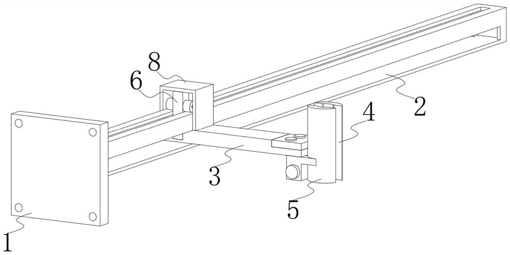
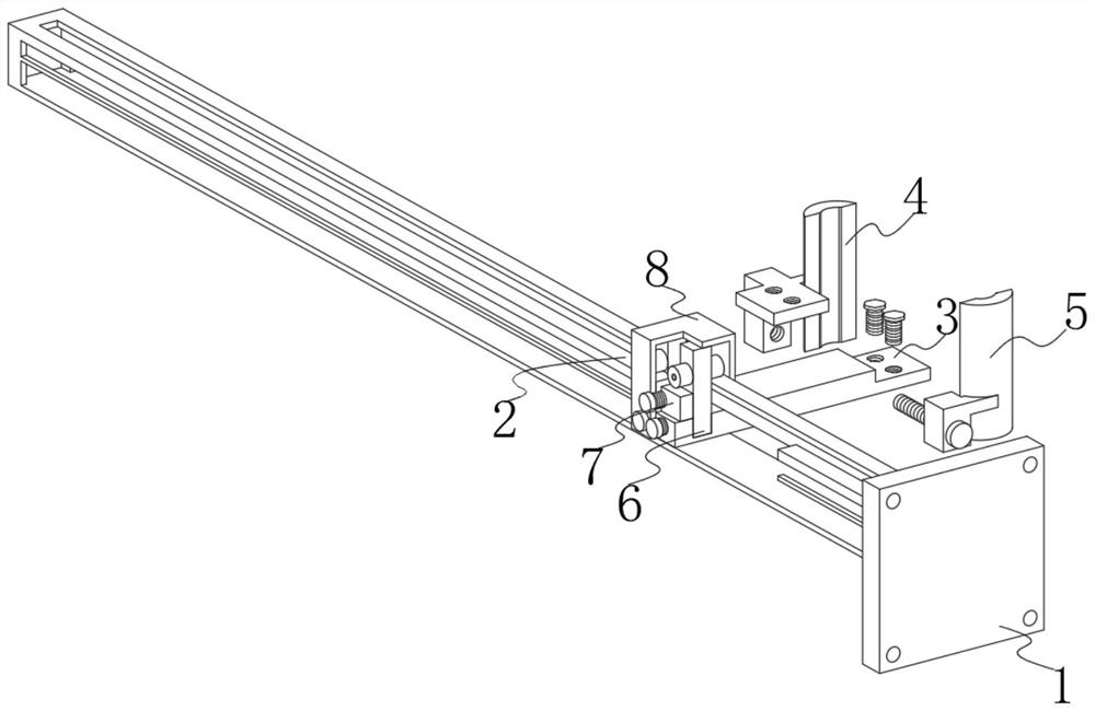
[0026] see Figure 1-4 , the present invention provides a technical solution: a vertical wire clamp, including a base 1, a connecting block 3, a limit frame 8 and a block 7, a guide rod 2 is welded at the center of the outer surface of one side of the base 1, and the guide r...


PUM


Abstract

The invention discloses a vertical wire clamp, and relates to the technical field of wire clamp equipment. The vertical wire clamp comprises a base, a connecting block, a limiting frame and a clamping block, a guide rod is welded to the center of the outer surface of one side of the base, a first limiting groove is formed in the position, close to the bottom edge, of the outer surface of one side of the guide rod, a first mounting groove is formed in the center of the top of the guide rod, and a fixed clamping block is fixedly connected to the position, close to the side edge, of the top of the connecting block through a first bolt; a connecting groove is formed in the top, close to the edge of the other side, of the connecting block, and a limiting block is slidably embedded in the connecting groove. When the vertical wire clamp is used, the whole vertical wire clamp can be stably installed through the base, a limiting block and the limiting frame are matched with a third bolt to effectively limit installation of the connecting block, so that the connecting block can effectively move in a guide rod, and when the connecting block moves to a proper position of the guide rod, a fourth bolt is controlled and thus the limiting frame is matched with the clamping block to effectively clamp the guide rod, so that the position of the connecting block is effectively fixed.

Description

technical field [0001] The invention relates to the technical field of wire clamp equipment, in particular to a vertical wire clamp. Background technique [0002] Wire clamps are metal accessories made of iron or aluminum that can be fixed on the cable. Most of them need to bear large tension during operation, and some also need to ensure good electrical contact at the same time. However, most devices in the prior art are fixed The length of the connecting rod is installed and set, so that the device needs to be replaced with different lengths of connecting rods according to the actual use, which affects the convenience of the actual use of the equipment to a certain extent. Effects are somewhat adversely affected. Contents of the invention [0003] The invention provides a vertical cable clamp, which can effectively adjust the use position of the equipment according to the actual use conditions after use, effectively improving the convenience of the actual use of the equ...

Claims


Application Information

Patent Timeline
IPC IPC(8): H02G3/02H02G7/14H02G7/05
CPCH02G3/02H02G7/14H02G7/05
Inventor 金浩金宝洁闫昌干何伟蔡宇黄豪威林巍
Owner ZHONGWANG ELECTRIC POWER TECH CO LTD
Learn More