Permanent magnet type switched reluctance motor and control method thereof

A switched reluctance motor and control method technology, applied in the direction of magnetic circuit shape/style/structure, magnetic circuit, electric components, etc., can solve the problems of high paste strength requirements, waste of internal space of the motor, and low efficiency of the motor, and achieve Less demagnetization, easier design, and improved reliability

Pending Publication Date: 2021-05-14
SHENZHEN HUAYIN POWER TECH CO LTD
View PDF2 Cites 0 Cited by
  • Summary
  • Abstract
  • Description
  • Claims
  • Application Information

AI Technical Summary

Problems solved by technology

However, the permanent magnets in the permanent magnet switched reluctance motor are installed on the top of the salient poles of the rotor iron core, which belong to the permanent magnets pasted on the surface. Considering the influence of high-speed centrifugal force, the paste strength requirements are high; When the air gap is too large at the edge, it will cause the motor to be inefficient
In addition, each stator core of the permanent magnet switched reluctance motor is equipped with only one phase winding, and the adjacent salient pole windings are wound in opposite directions. A stator core and a rotor core are aligned as a pair and run along the Axially distributed in pairs, the space between the cores of this structure needs to be reserved at the end of the winding, which wastes the internal space of the motor and causes a decrease in power density

Method used


Image

  • Permanent magnet type switched reluctance motor and control method thereof

Examples


Embodiment 1

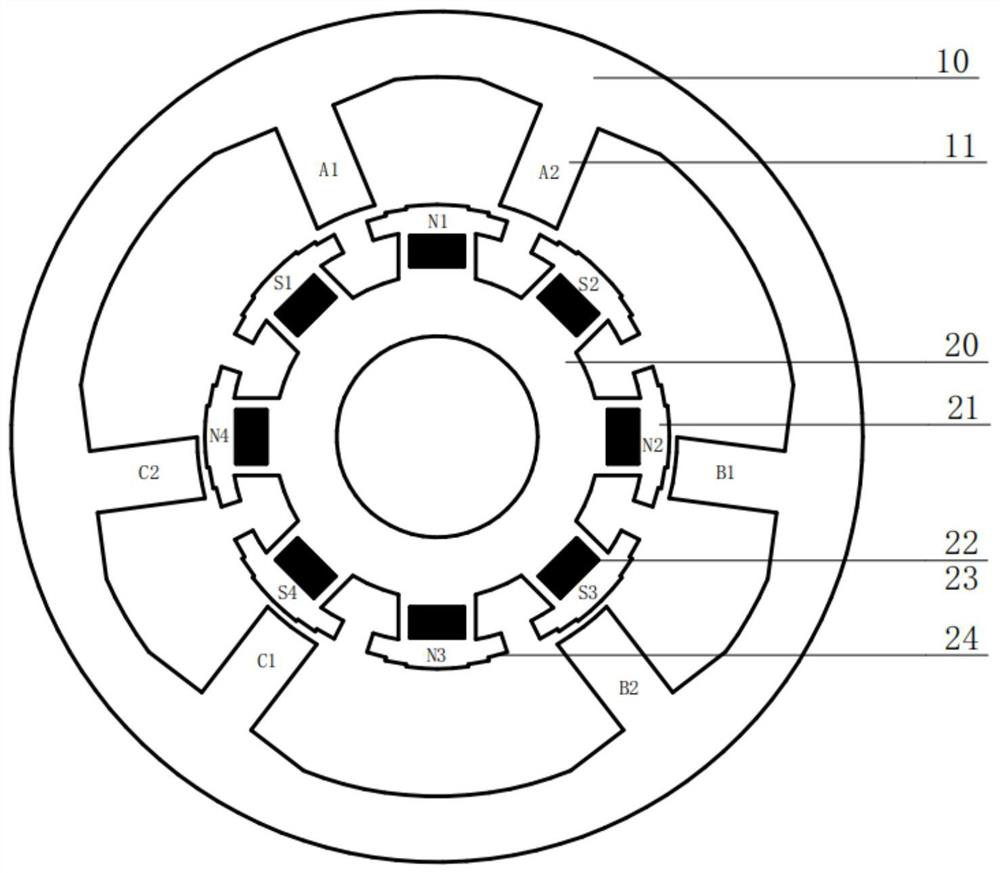
[0043] see figure 1 , a permanent magnet switched reluctance motor, comprising a stator core 10 and a rotor core 20, the number of phases of the motor is 3, the number of salient poles of the stator core 10 is 6, and the number of groups k=1; On the stator core 10, the salient poles 11 of the stator cores belonging to the same phase are arranged adjacent to each other, as shown in the figure, the salient poles 11 of the stator core belonging to the A phase are arranged adjacently and concentrated, and the stator cores belonging to the B phase The salient poles 11 of the core are arranged adjacent to each other, and the salient poles 11 of the stator core belonging to the C phase are arranged adjacent to each other, and the phase winding is installed so that the adjacent salient poles in the phase are under the action of the exciting current. Form adjacent pairs of magnetic poles; the number of salient poles of the rotor core 20 is 8, and an axial through hole 23 is arranged in...


PUM


Abstract

The invention discloses a permanent magnet type switched reluctance motor and a control method thereof, and belongs to the field of switched reluctance motors. The number of salient poles of a stator core of the permanent magnet type switched reluctance motor is m, the number of salient poles of a rotor core is n, n is larger than m and is an even number, n is the minimum even number in the value range, a phase number of the motor is q, and q is larger than or equal to 3 and is a natural number; the salient poles of the stator core belonging to the same phase on the stator core are adjacently and intensively arranged, and the winding of the phase is installed, so that the adjacent salient poles in the phase form adjacent magnetic pole pairs under the action of exciting current of the winding of the phase; and axial through holes are formed in salient pole bodies of the rotor iron cores, permanent magnets are installed in the axial through holes, the magnetic pole directions of the permanent magnets are radial, and the magnetic pole directions of the permanent magnets in the salient poles of the adjacent rotor iron cores are opposite. The power density of the switched reluctance motor is remarkably improved by combining the reluctance features and the permanent magnet features of the motor.

Description

technical field [0001] The invention relates to the field of switched reluctance motors, in particular to a permanent magnet switched reluctance motor and a control method thereof. Background technique [0002] The phases of the switched reluctance motor circulate electricity in turns, and the power density is low. The phases of the permanent magnet motor are energized in combination, and the power density is high. Therefore, how to combine the motor reluctance characteristics and permanent magnet characteristics to improve the power density of the switched reluctance motor is a technical problem to be solved in the existing switched reluctance motor. [0003] The invention patent with the publication number CN106130277A discloses a permanent magnet switched reluctance motor, including a motor casing, a stator core, a winding, a rotor core, a permanent magnet, and a motor shaft. The permanent magnet switched reluctance motor The motor consists of k stator cores and k rotor...

Claims


Application Information

Patent Timeline
Patent Type & Authority Applications(China)
IPC IPC(8): H02K1/14H02K1/24H02K1/27
CPCH02K1/14H02K1/246H02K1/274H02K2213/03
Inventor 顾志强李运忠刘正昂
Owner SHENZHEN HUAYIN POWER TECH CO LTD
Why Eureka
Try Eureka