New rcc circuit based on mos device

A MOS device and circuit technology, applied in the field of new RCC circuits, can solve the problems of unfavorable product power density and large junction capacitance, and achieve the effects of extending the application power level, improving circuit efficiency, and improving reliability control

Active Publication Date: 2022-04-08
扬州江新电子有限公司
View PDF1 Cites 0 Cited by
  • Summary
  • Abstract
  • Description
  • Claims
  • Application Information

AI Technical Summary

Problems solved by technology

The disadvantage is that due to the large junction capacitance of the traditional Si-based MOS tube, after weighing loss, cost, EMI and other factors, its operating frequency is generally only between 30kHz-100kHz, which is not conducive to improving the power density of the product

Method used


Image

  • New rcc circuit based on mos device
  • New rcc circuit based on mos device
  • New rcc circuit based on mos device

Examples


Embodiment 1

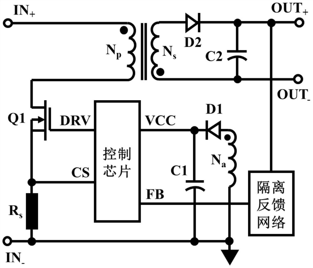
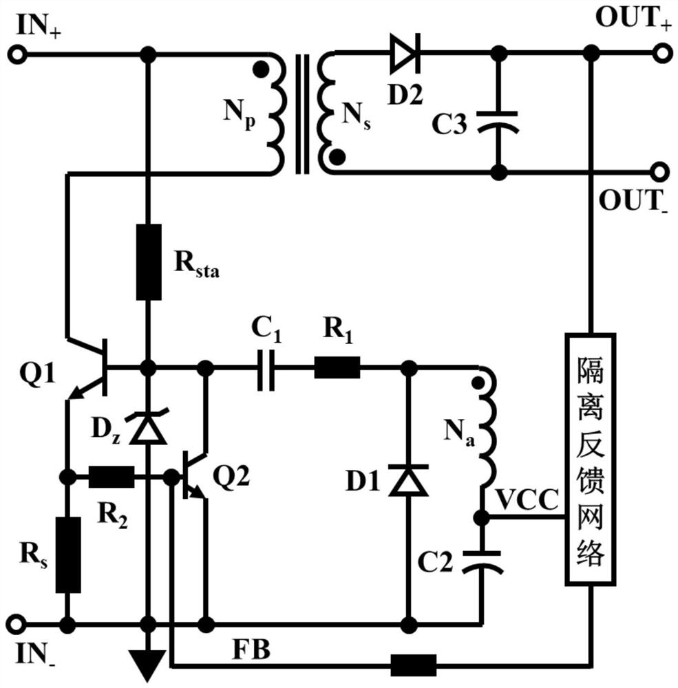
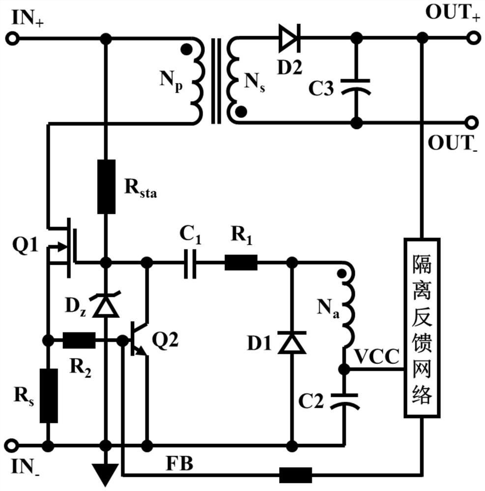
[0034] The new RCC circuit based on MOS devices includes: start-up circuit, power conversion circuit, protection circuit, Zener diode Dz1, voltage detection and transmission circuit, self-excited drive and cycle-by-cycle current detection circuit, output rectification circuit;

[0035] The start-up circuit is composed of a resistor Rsta, one end is connected to the positive line of the power input, and the other end is connected to the cathode of the Zener diode Dz1; Rsta is the high-voltage start-up resistor of Q1, generally set to 680kΩ-3MΩ;

[0036] The power conversion circuit is composed of the winding Np of the transformer, the main power transistor Q1 and the feedback function transistor Q2. Q1 is an enhanced LDMOS device, the gate of which is connected to the cathode of the Zener diode Dz1, the source is connected to the anode of the Zener diode Dz1 and Grounded, the terminal with the same name of the winding Np is connected to the input positive line, the terminal with...


PUM


Abstract

The invention discloses a novel RCC circuit based on MOS devices, which adopts the on-chip design of Q1 and Q2 dual transistors, and the two transistors share one wafer, thereby reducing volume, reducing cost and improving reliability control. The circuit continues to use the third auxiliary winding Na in the main transformer of the RCC circuit, and the self-excited drive chamber in the positive feedback mode automatically provides the drive signal for Q1 without the need for a control chip. The circuit further adopts an integrated high-frequency current cycle-by-cycle detection scheme, which shares a coil with the self-excited drive cavity, which saves the current detection resistor and realizes lossless current detection. The circuit also adopts the integral feedback method to realize the primary side feedback. By integrally calculating the drain voltage of Q1 during the off time, the output voltage information is obtained indirectly, so as to realize real-time and precise regulation of the output voltage.

Description

technical field [0001] The invention relates to a novel RCC circuit based on MOS devices. Background technique [0002] With the rapid development of science and technology and the response to the national low energy consumption strategy, the switching power supply market is showing a trend of continuous growth year by year, and the switching power supply field has higher and higher requirements for efficiency and size. Due to the simple structure, few components, high reliability, and low cost of the flyback converter, coupled with the use of inductive energy storage, the primary current is often large, the transformer leakage inductance is large, and its maximum duty cycle is usually limited Within 0.4, the maximum power of the flyback circuit is greatly limited. Therefore, in the case of low power less than 75W, the flyback converter has developed into a dominant position in the market. There is a special circuit form in the flyback converter, that is, the self-excited f...

Claims


Application Information

Patent Timeline
Patent Type & Authority Patents(China)
IPC IPC(8): H02M3/338H02M1/08H02M1/44G01R19/00
CPCH02M3/3385H02M1/08H02M1/44G01R19/0007
Inventor 庄宗其高潮朱晨豪杨周姚世强周祥兵陈敦军
Owner 扬州江新电子有限公司
Why Eureka
Try Eureka