Self-excitation driving and power conversion circuit based on GaN HEMT device

A technology for converting circuits and powers, which can be used in conversion devices and instruments that convert DC power input into DC power output and output power, and can solve problems such as unfavorable product power density and large junction capacitance.

Active Publication Date: 2021-05-14
扬州江新电子有限公司
View PDF2 Cites 2 Cited by
  • Summary
  • Abstract
  • Description
  • Claims
  • Application Information

AI Technical Summary

Problems solved by technology

The disadvantage is that due to the large junction capacitance of the traditional Si-based MOS tube, after weighing loss, cost, EMI and other

Method used


Image

  • Self-excitation driving and power conversion circuit based on GaN HEMT device
  • Self-excitation driving and power conversion circuit based on GaN HEMT device
  • Self-excitation driving and power conversion circuit based on GaN HEMT device

Examples


Embodiment 1

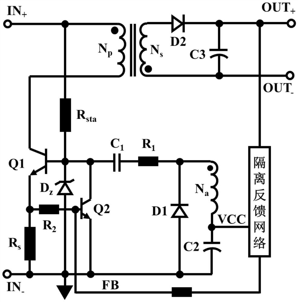
[0036] This self-excited drive and power conversion circuit based on GaN HEMT devices includes: start-up circuit, power conversion circuit, protection circuit, Zener diode Dz1, isolated feedback network, self-excited drive and cycle-by-cycle current detection circuit, drive buffer, output rectifier circuit;

[0037] The start-up circuit is composed of a resistor Rsta, one end is connected to the positive line of the power input, and the other end is connected to the cathode of the Zener diode Dz1, Rsta is the high-voltage start-up resistor of Q1, generally set to 680kΩ-3MΩ;

[0038] The power conversion circuit is composed of the winding Np of the transformer, the main power tube Q1 and the feedback function tube Q2. Q1 is an enhanced GaN HEMT device, the gate of which is connected to the cathode of the Zener diode Dz1, and the source is connected to the anode of the Zener diode Dz1. And grounded, the terminal with the same name of the winding Np is connected to the input posi...

Embodiment 2

[0049] The structure of this embodiment is basically the same as that of Embodiment 1, the difference is that the drive buffer includes resistors R101, R102, R103, R104, R106, NOT gates U101A, U101C, U101D, DC blocking capacitors C101, C102, Zener diodes Dz101, Dz102, and C1 pass the drive signal to the NOT gate U101A after being divided by R101, R102. After the level is reversed, it first passes through the voltage regulator and filter network DZ101, R103, and C101, and then passes through DZ102, R104, and C102 to the next Level NOT gates U101C, U101D, the level is reversed twice and then passed to the gate of Q1 through the resistor R106. The drive buffer generates inverting input and output logic, such as outputting a low level when the input is high.

[0050] The non-inverting and inverting outputs can also be integrated into the same driver buffer, and users can choose to connect according to their needs.


PUM


Abstract

The invention discloses a self-excitation driving and power conversion circuit based on a GaN HEMT device. The self-excitation driving and power conversion circuit adopts the novel GaN-based HEMT device, and improves the working frequency of the circuit to MHz. The device adopts a silicon substrate, and adopts on-chip design of a Q1 transistor and a Q2 transistor, wherein the two transistors share one wafer, so that the size is reduced, the cost is reduced, and the reliability control is improved. The device further adopts an integrated anti-parallel diode structure, so that the reverse conduction characteristic of the device is improved. According to the self-excitation driving and power conversion circuit, through using a third auxiliary winding Na in a main transformer of a power circuit, a self-excitation driving cavity in a positive feedback mode is adopted to automatically provide a driving signal for Q1, a control chip is not needed, and the driving of the Q1 needs to be ensured to be reliable through a special driving buffer circuit for the GaN HEMT device. The self-excitation driving and power conversion circuit further adopts an integrated high-frequency current cycle-by-cycle detection scheme, and shares one coil with the self-excitation driving cavity, so that a current detection resistor is omitted, and lossless current detection is realized.

Description

technical field [0001] The invention relates to a self-excited drive and power conversion circuit based on GaNHEMT devices. Background technique [0002] With the rapid development of science and technology and the response to the national low energy consumption strategy, the switching power supply market is showing a trend of continuous growth year by year, and the switching power supply field has higher and higher requirements for efficiency and size. Due to the simple structure, few components, high reliability, and low cost of the flyback converter, coupled with the use of inductive energy storage, the primary current is often large, the transformer leakage inductance is large, and its maximum duty cycle is usually limited Within 0.4, the maximum power of the flyback circuit is greatly limited. Therefore, in the case of low power less than 75W, the flyback converter has developed into a dominant position in the market. There is a special circuit form in the flyback conv...

Claims


Application Information

Patent Timeline
IPC IPC(8): H02M3/338H02M1/08H02M1/44G01R15/14G01R19/00
CPCH02M3/338H02M1/08H02M1/44G01R15/14G01R19/0092Y02B70/10
Inventor 王玉雯高潮庄紫怡吉怡悦周祥兵陈敦军
Owner 扬州江新电子有限公司
Why Eureka
Try Eureka