Injection pump and injection system
A technology for syringe pumps and syringes, which is applied in the direction of syringes, automatic injectors, hypodermic injection devices, etc., and can solve problems such as mistouching of syringes, affecting the appearance, and dust falling from grip handles and syringes
- Summary
- Abstract
- Description
- Claims
- Application Information
AI Technical Summary
Problems solved by technology
Method used
Image

Examples
Embodiment Construction
[0025] The following will be combined with the appended in the embodiment of the application Figure 1-5 , clearly and completely describe the technical solutions in the embodiments of the present application. Apparently, the described embodiments are only some of the embodiments of the present application, not all of them. Based on the embodiments in this application, all other embodiments obtained by persons of ordinary skill in the art without making creative efforts belong to the scope of protection of this application.
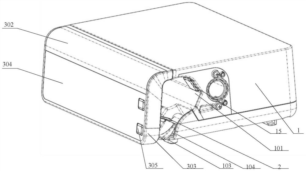
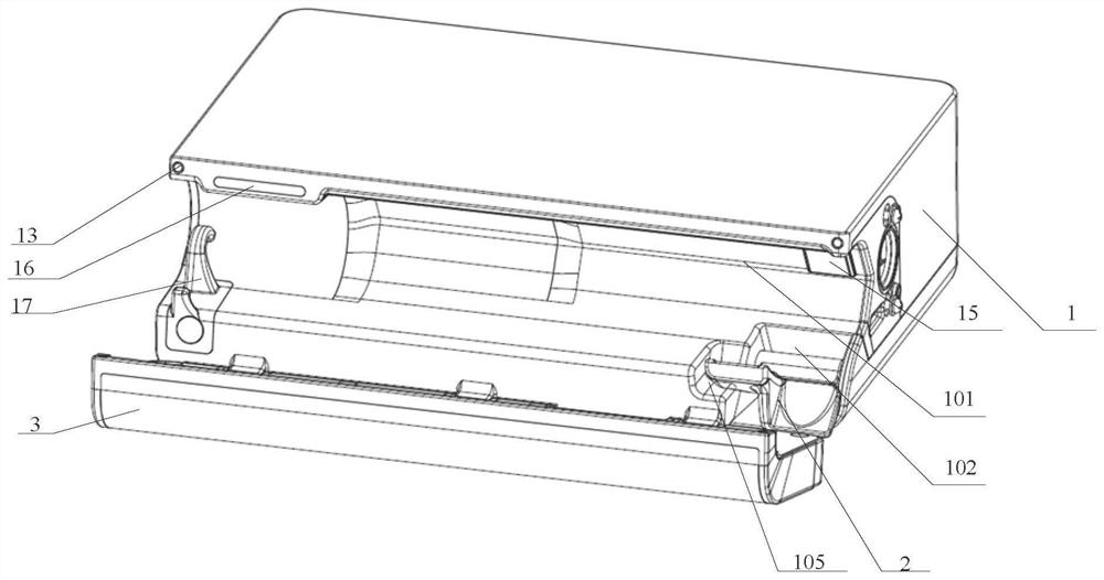
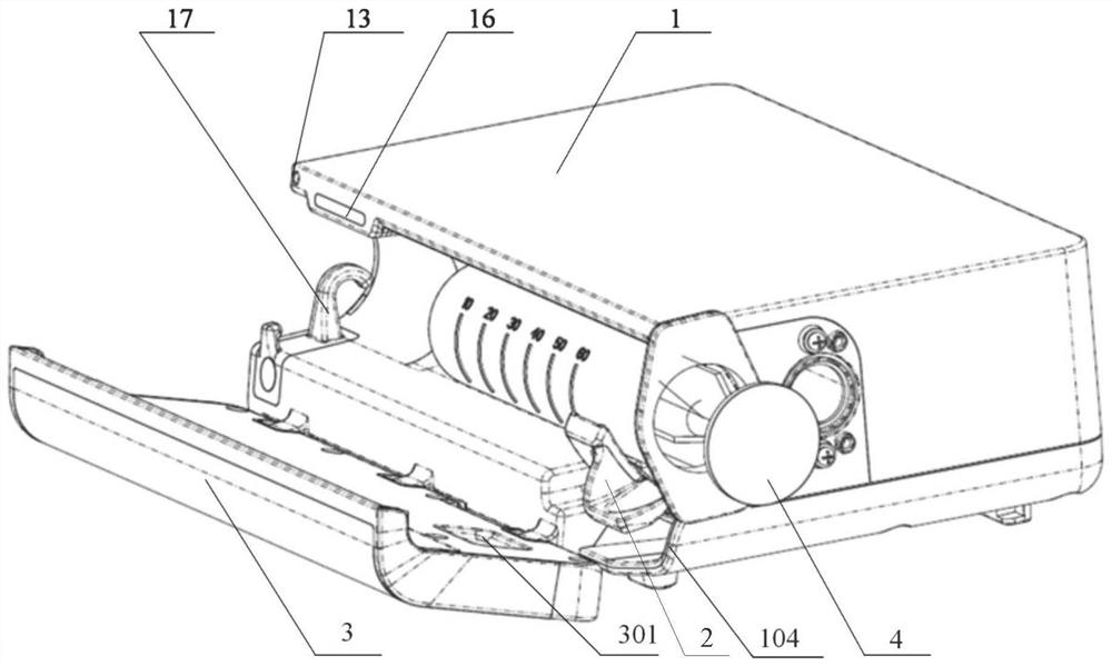
[0026] Such as Figure 1-3 As shown, the syringe pump provided by the embodiment of the present invention includes a pump body 1 , a clamp handle 2 and a pump door 3 , wherein the syringe pump is used in conjunction with a syringe 4 .
[0027] The syringe 4 includes a syringe body 401 and a syringe piston 402 , pushing the syringe piston 402 can output the medicinal liquid in the syringe body 401 . The syringe pump is also provided with a driving mechan...
PUM
 Abstract
Description
Claims
Application Information