
Cleaning and maintaining equipment for water conservancy gate

A gate and water conservancy technology, applied in the field of cleaning and maintenance equipment for water conservancy gates, can solve the problems of reducing the bearing capacity of steel gates, easy corrosion of steel, and affecting the safety of water conservancy projects.

Inactive Publication Date: 2021-05-18
深圳市善超商贸有限公司
View PDF0 Cites 0 Cited by
  • Summary
  • Abstract
  • Description
  • Claims
  • Application Information

AI Technical Summary

Problems solved by technology

[0002] Steel structure sluice gates are important components for controlling water levels in hydraulic structures such as hydropower stations, reservoirs, sluices, and ship locks. It is also eroded by water waves, sediment, and other floating objects. Steel is easily corroded, which significantly reduces the bearing capacity of steel gates and seriously affects the safety of water conservancy projects. Some existing maintenance equipment for water conservancy gates is difficult to achieve Better cleaning and maintenance effect, a kind of cleaning and maintenance equipment for water conservancy gates described in the present invention can solve the above problems

Method used


Image

  • Cleaning and maintaining equipment for water conservancy gate
  • Cleaning and maintaining equipment for water conservancy gate
  • Cleaning and maintaining equipment for water conservancy gate

Examples


Embodiment Construction

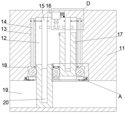
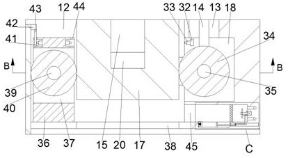
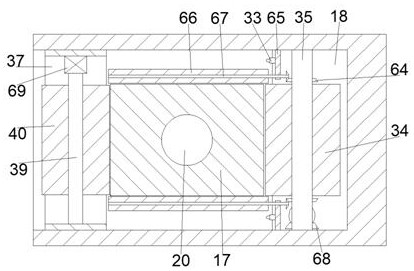
[0019] Combine below Figure 1-5 The present invention is described in detail, wherein, for the convenience of description, the orientations mentioned below are defined as follows: figure 1 The up, down, left, right, front and back directions of the projection relationship itself are the same.

[0020] The cleaning and maintenance equipment for a water conservancy gate according to the present invention includes a gate box 11, a gate chamber 12 is arranged in the gate box 11, and a communication chamber 38 is connected to the lower side of the gate chamber 12, and the gate chamber 12 The upper wall is communicated with a switch chamber 16, the front and rear walls of the switch chamber 16 are slidingly connected with a switch block 21, the lower side of the communication chamber 38 is connected with a left and right flow chamber 19, and the left and right sides of the gate chamber 12 are provided with There is a symmetrical rotating rod chamber 13, the left and right walls of...


PUM


Abstract

The invention discloses cleaning and maintaining equipment for a water conservancy gate. The cleaning and maintaining equipment comprises a gate box, a gate cavity is formed in the gate box, a communicating cavity is formed in the lower side of the gate cavity in a communicating mode, a switching cavity is formed in the upper wall of the gate cavity in a communicating mode, switching blocks are connected to the front wall and the rear wall of the switching cavity in a left-right sliding mode, the lower side of the communicating cavity communicates with a left-right through flowing cavity, the left side and the right side of the gate cavity are provided with symmetrical rotating rod cavities, the left wall and the right wall of the gate cavity communicate with symmetrical cleaning wheel cavities located on the lower sides of the rotating rod cavities, the upper walls of the cleaning wheel cavities communicate with the lower sides of the rotating rod cavities, symmetrical collecting cavities are formed in the lower sides of the left cleaning wheel cavity and the right cleaning wheel cavity, and the sides, close to each other, of the left collecting cavity and the right collecting cavity communicate with the left wall and the right wall of the gate cavity. The left gate and the right gate work respectively, and the front end surfaces, the rear end surfaces, the left end surfaces and the right end surfaces of the gates can be fully cleaned independently while the gates are recycled and cleaned.

Description

technical field [0001] The invention relates to the related fields of water conservancy gates, in particular to cleaning and maintenance equipment for water conservancy gates. Background technique [0002] Steel structure sluice gates are important components for controlling water levels in hydraulic structures such as hydropower stations, reservoirs, sluices, and ship locks. It is also eroded by water waves, sediment, and other floating objects. Steel is easily corroded, which significantly reduces the bearing capacity of steel gates and seriously affects the safety of water conservancy projects. Some existing maintenance equipment for water conservancy gates is difficult to achieve Better cleaning and maintenance effect, a kind of cleaning and maintenance equipment for water conservancy gates described in the present invention can solve the above problems. Contents of the invention [0003] In order to solve the above problems, this example designs a cleaning and mainte...

Claims


Application Information

Patent Timeline
IPC IPC(8): B08B1/04B08B1/00B08B3/02B08B15/04B30B9/30E02B7/20E02B8/00
CPCB08B3/02B08B15/04B30B9/30E02B7/20E02B8/00B08B1/50B08B1/32
Inventor 廖晶丽
Owner 深圳市善超商贸有限公司
Learn More