
Plate shearing machine with positioning mechanism

A positioning mechanism and shearing machine technology, applied in shearing equipment, shearing devices, manufacturing tools, etc., can solve problems such as affecting the quality of steel plate shearing, unable to complete the shearing work better, and lack of stable positioning and fixing.

Pending Publication Date: 2021-05-18
NANTONG MTR MACHINE TOOL CO LTD
View PDF0 Cites 1 Cited by
  • Summary
  • Abstract
  • Description
  • Claims
  • Application Information

AI Technical Summary

Problems solved by technology

[0004] The purpose of the present invention is to provide a plate shearing machine with a positioning mechanism to solve the problem that the existing plate shearing machine in the above background technology is used to shorten the steel plate, because the steel plates are mostly placed directly, there is no stable Positioning and fixing can easily lead to uneven cuts and vibrations during the shearing process of the steel plate, which cannot complete the shearing work better and affect the quality of the steel plate shearing

Method used


Image

  • Plate shearing machine with positioning mechanism
  • Plate shearing machine with positioning mechanism
  • Plate shearing machine with positioning mechanism

Examples


Embodiment Construction

[0019]Next, the technical solutions in the embodiments of the present invention will be apparent from the embodiment of the present invention, and it is clearly described, and it is understood that the described embodiments are merely embodiments of the present invention, not all of the embodiments. Based on the embodiments of the present invention, there are all other embodiments obtained without making creative labor without making creative labor premises.

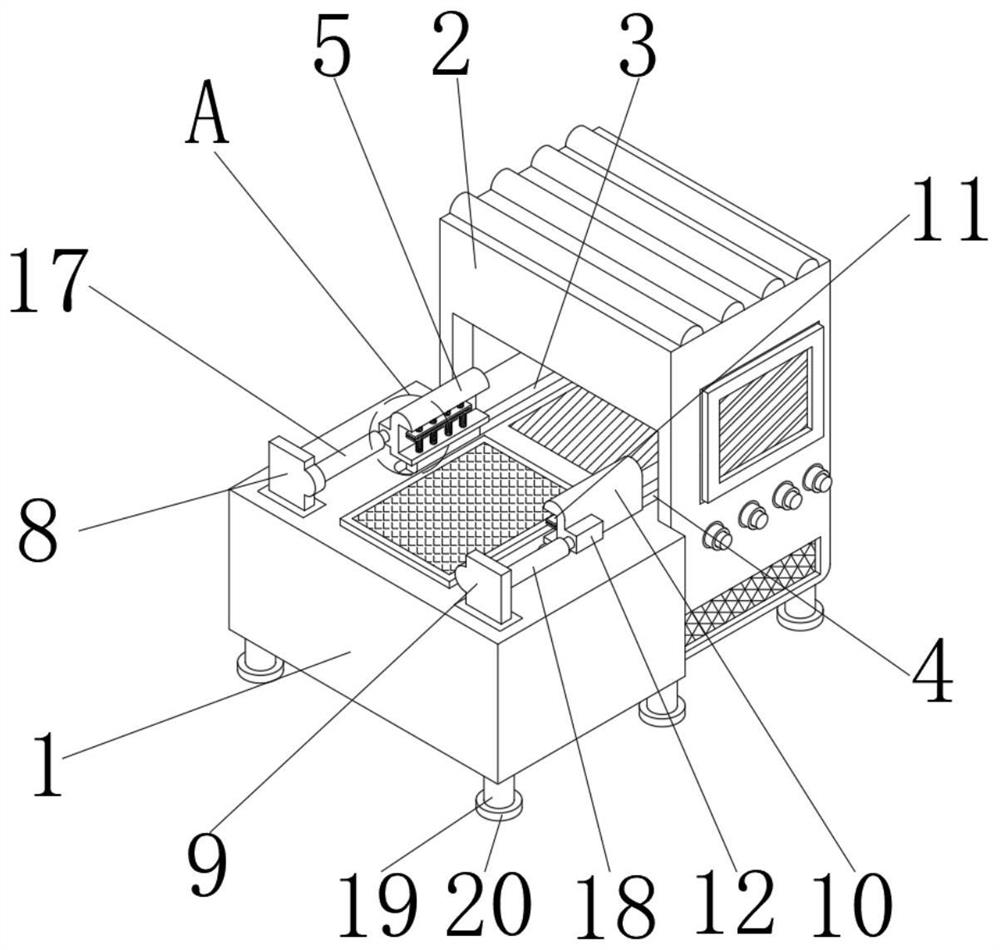
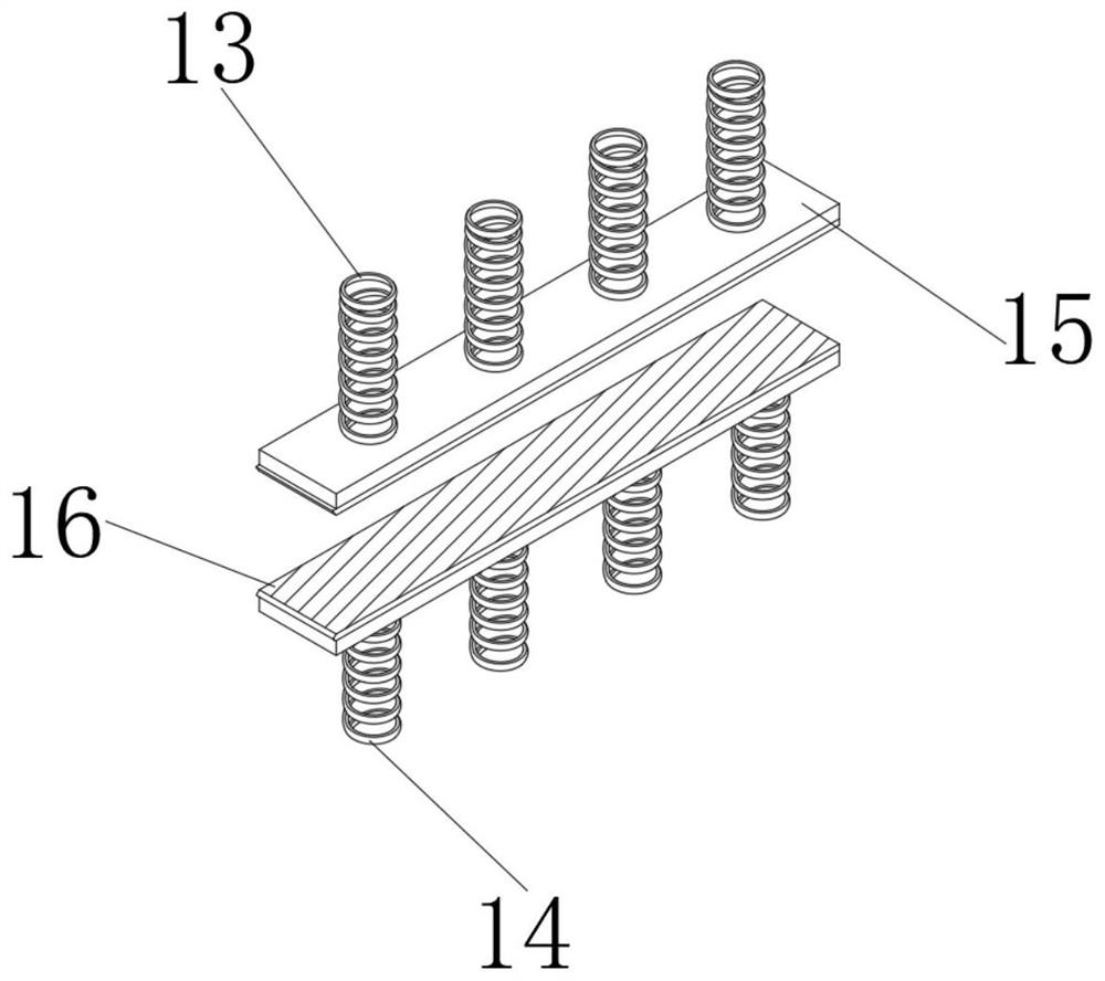
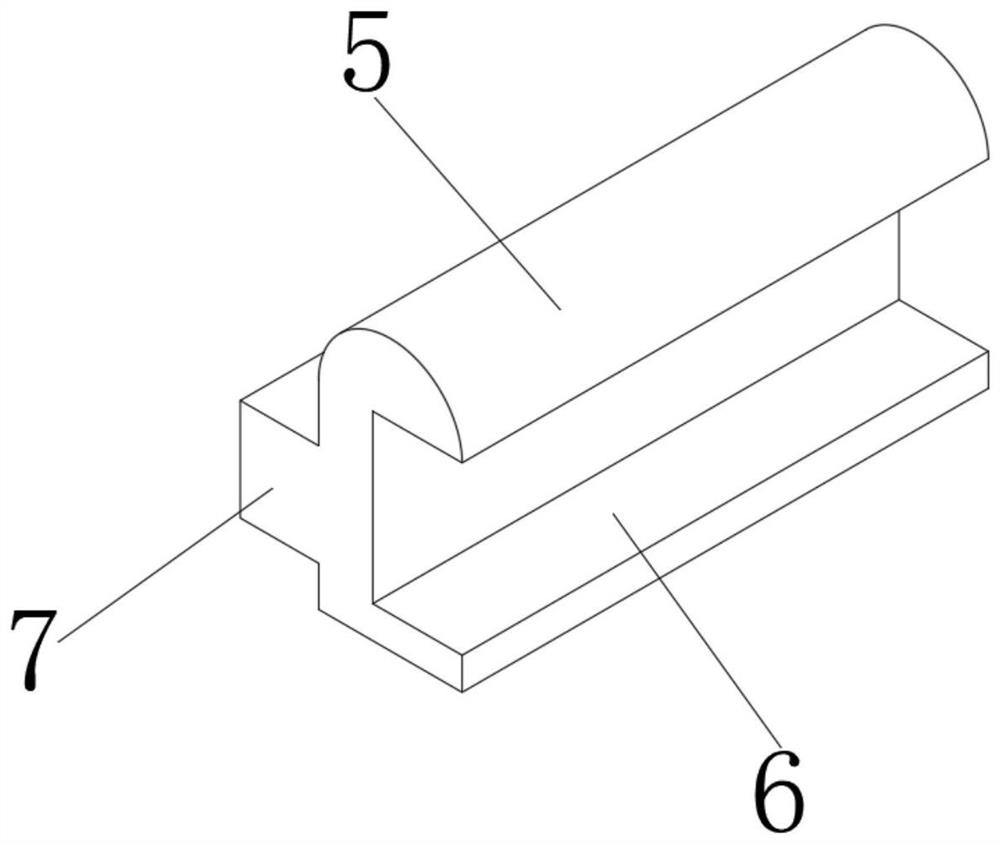
[0020]SeeFigure 1-4One embodiment of the present invention is provided: a shearing machine having a positioning mechanism, including a table 1, a table 1 side having a shear machine body 2, and a top surface of the table 1 set from left to right? There is a first sliding rail 3 and a second sliding rail 4, and the internal activity of the first sliding rail 3 is connected to the first positioning frame 5, and the first positioning slot 6 is opened, and the first position frame 5 is opened. On the other side, the first connection ...


PUM


Abstract

The invention relates to the technical field of plate shearing machine equipment, in particular to a plate shearing machine with a positioning mechanism. The plate shearing machine comprises a worktable, a plate shearing machine body, a first sliding rail, a second sliding rail and a first positioning frame, a first positioning groove is formed in one side of the first positioning frame, a first connecting block is fixedly connected to the other side of the first positioning frame, a first supporting plate and a second supporting plate are sequentially and fixedly connected to the upper surface of the workbench from left to right. A steel plate can be quickly positioned and fixed through the first positioning frame and the second positioning frame, in the actual use process, a worker firstly places the two ends of the steel plate needing to be subjected to plate shearing operation into the first positioning frame and the second positioning frame correspondingly, a first spring assembly and a second spring assembly can respectively push a first clamping plate and a second clamping plate to firmly jack and fix the steel plate in a positioning groove of a positioning frame, so that the steel plate can be stably fixed through the design.

Description

Technical field[0001]The present invention relates to the technical field of shearing machine equipment, and is specifically a shearing machine having a positioning mechanism.Background technique[0002]The shearing machine is a machine with a blade that is opposed to another blade to a backward line motion shearing sheet. It is an upper blade and a fixed lower blade that uses a reasonable blade gap, applied a shear of a variety of thickness. Force, the sheet is separated according to the size of the required size. The shear machine belongs to one of the forging machinery. The main role is that the metal processing industry is widely used in aviation, light industry, metallurgy, chemical, construction, ship, automobile, electricity, electrical appliances, and decoration providing special machinery. And a set of equipment.[0003]After shearing the shear machine, it should be ensured that the straightness and flatness requirements of the shear shear shear surface, and minimize the plate ...

Claims


Application Information

Patent Timeline
IPC IPC(8): B23D33/02B23D33/10B23D15/08
CPCB23D15/08B23D33/02B23D33/10
Inventor 吕建峰
Owner NANTONG MTR MACHINE TOOL CO LTD
Learn More