Joint movement mechanism and robot

A technology of joint motion and transmission mechanism, applied in the field of mechanical transmission, can solve the problems of low center of mass of robot and large torque demand of joint steering gear.

Active Publication Date: 2021-05-18
UBTECH ROBOTICS CORP LTD
View PDF7 Cites 0 Cited by
  • Summary
  • Abstract
  • Description
  • Claims
  • Application Information

AI Technical Summary

Problems solved by technology

[0003] The purpose of the embodiments of the present invention is to provide a joint motion mechanism and a robot to solve the technical problems in the prior art that the center of mass of the robot is too low and the torque of the joint steering gear is relatively large

Method used


Image

  • Joint movement mechanism and robot
  • Joint movement mechanism and robot
  • Joint movement mechanism and robot

Examples


Embodiment Construction

[0023] In order to make the technical problems, technical solutions and beneficial effects to be solved by the present invention clearer, the present invention will be further described in detail below in conjunction with the accompanying drawings and embodiments. It should be understood that the specific embodiments described here are only used to explain the present invention, not to limit the present invention.

[0024] It should be noted that when an element is referred to as being “fixed” or “disposed on” another element, it may be directly on the other element or be indirectly on the other element. When an element is referred to as being "connected to" another element, it can be directly connected to the other element or indirectly connected to the other element.

[0025] It is to be understood that the terms "length", "width", "top", "bottom", "front", "rear", "left", "right", "vertical", "horizontal", "top" , "bottom", "inner", "outer" and other indicated orientations...


PUM


Abstract

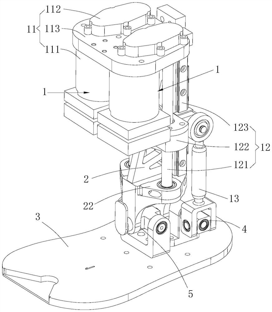
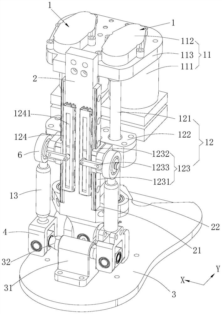
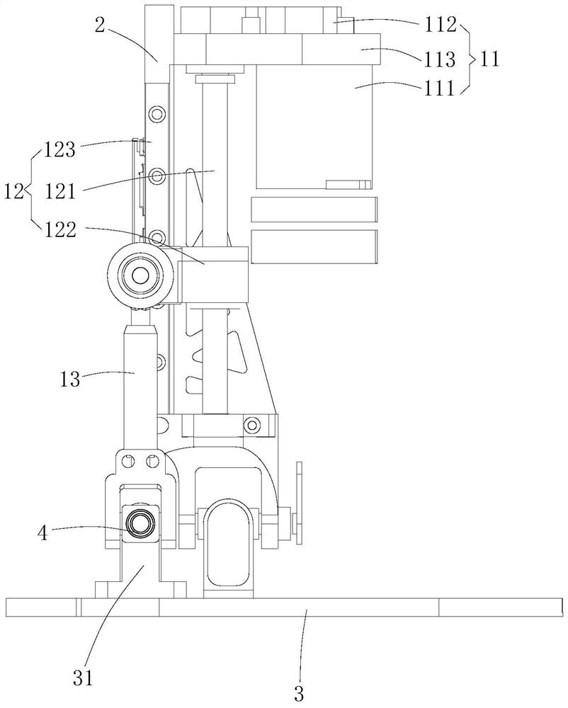
The invention provides a joint movement mechanism and a robot. The joint movement mechanism comprises an execution piece, a fixing frame rotationally connected to the execution piece and two transmission mechanisms. In the first direction, the two transmission mechanisms are correspondingly arranged on the two opposite sides of the fixing frame, in the second direction, the two transmission mechanisms are correspondingly arranged on the same side of the fixing frame, the two transmission mechanisms comprise driving assemblies, lead screw assemblies and connecting rod structures, one ends of the connecting rod structures are rotationally connected to the moving ends of the lead screw assemblies, and the other ends are rotationally connected to the execution piece. According to the joint movement mechanism and the robot, the execution piece is driven to pitch and roll through the lead screw assemblies and the connecting rod structures, the positions of the driving assemblies are far away from the execution piece, when the joint movement mechanism is applied to the robot, the positions of the driving assemblies are high, and the mass center of the robot can be increased. In the length direction of the lead screw assemblies, the lead screw structures and the connecting rod structures partially coincide, too large length space is not occupied, and the structure is more compact.

Description

technical field [0001] The invention belongs to the technical field of mechanical transmission, and more specifically relates to a joint motion mechanism and a robot. Background technique [0002] Most of the joints of legged robots are dual-degree-of-freedom, that is, they can perform pitch and roll motions at the same time, so two motors are needed to drive them to control their pitch and roll angles. The current steering gear arrangement is partly orthogonal, especially for small and medium-sized robots. This often results in a large size of the joints of the robot, a large overall inertia, a relatively low center of mass, and a relatively large torque requirement for the joint steering gear, resulting in a decline in the robot's motion performance. Contents of the invention [0003] The purpose of the embodiments of the present invention is to provide a joint motion mechanism and a robot to solve the technical problems in the prior art that the center of mass of the r...

Claims


Application Information

Patent Timeline
Patent Type & Authority Applications(China)
IPC IPC(8): B25J17/00B25J9/12B25J9/10
CPCB25J17/00B25J9/126B25J9/10Y02T10/7072
Inventor 汪文广杨雄威丁宏钰柴延辉
Owner UBTECH ROBOTICS CORP LTD
Why Eureka
Try Eureka