
Reinforcing and limiting structure and method for detachable suspension of trailer

A technology of limit structure and trailer, which is applied in the substructure, tractor-trailer combination, suspension, etc., can solve the problem of easy breakage of the suspension connection structure

Pending Publication Date: 2021-05-18
ZHUMADIAN CIMC HUAJUN VEHICLE
View PDF0 Cites 0 Cited by
  • Summary
  • Abstract
  • Description
  • Claims
  • Application Information

AI Technical Summary

Problems solved by technology

[0007] The purpose of the present invention is to address the deficiencies of the prior art, thereby providing a detachable suspension reinforcement for trailers that not only solves the problem of flexible disassembly and assembly of the suspension, but also solves the problem that the suspension connection structure is easily broken due to the influence of shear force for a long time And limit structure and method

Method used


Image

  • Reinforcing and limiting structure and method for detachable suspension of trailer
  • Reinforcing and limiting structure and method for detachable suspension of trailer
  • Reinforcing and limiting structure and method for detachable suspension of trailer

Examples


Embodiment 1

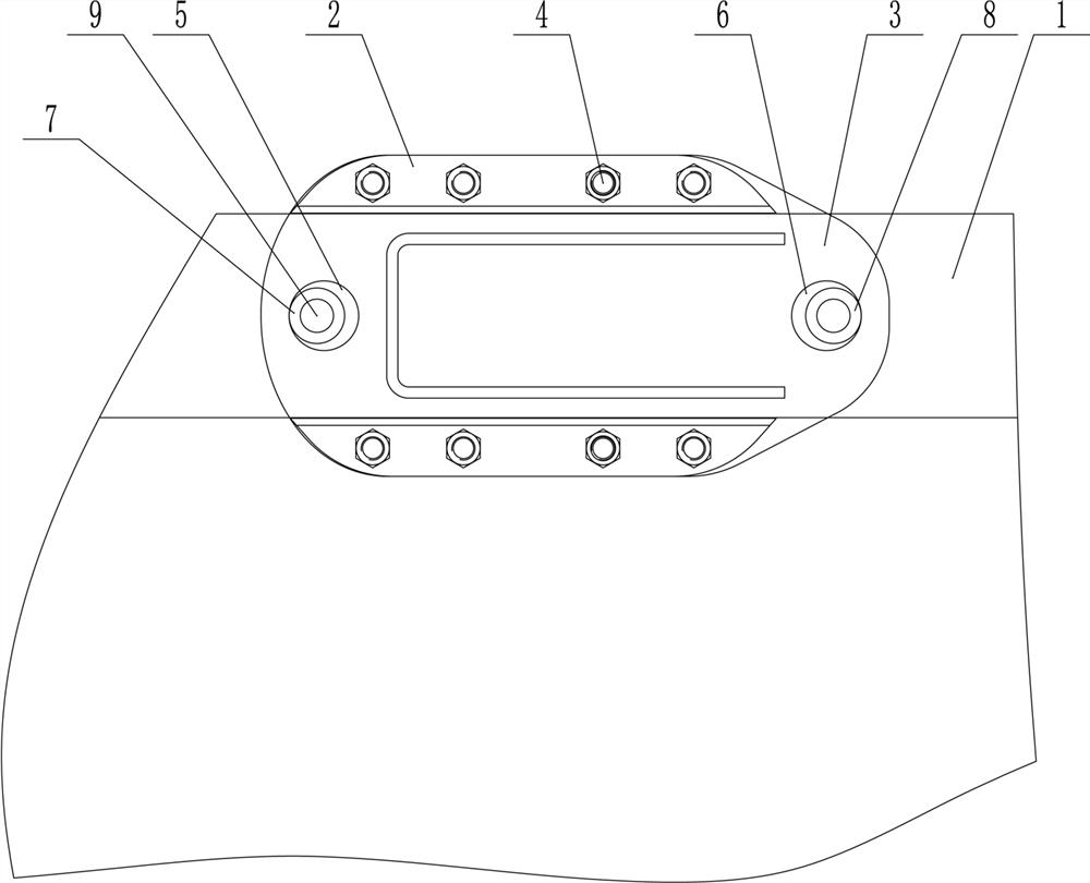
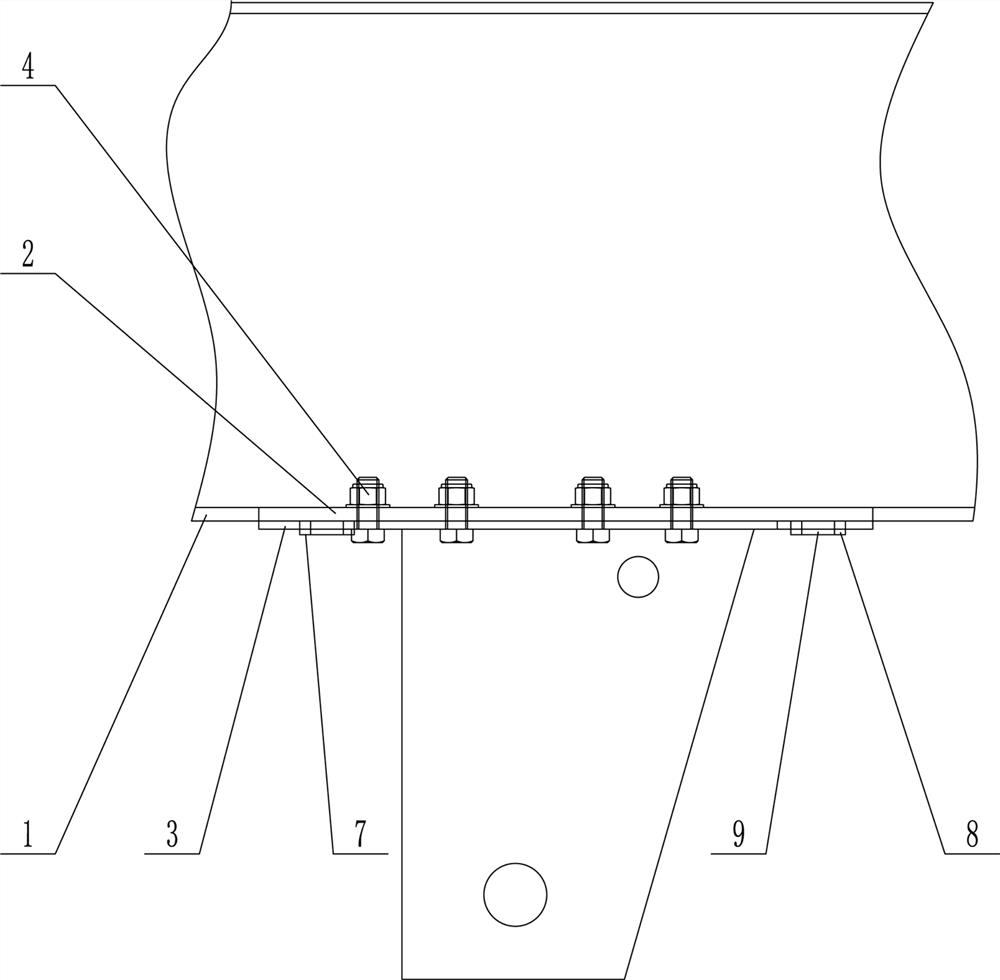
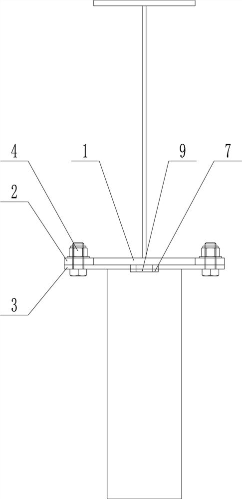
[0034] Such as Figure 1-Figure 5 As shown, a reinforcement and limit structure for a detachable suspension of a trailer, including a lower wing plate 1, a widened plate 2, a connecting hole on the widened plate, a suspension connecting plate 3, a front limit hole 5, and a rear limit Hole 6, circular front limiting plate 7 and circular rear limiting plate 8.

[0035] The connecting hole of the lower wing plate is provided on the suspension connecting plate, and the connecting hole of the lower wing plate corresponds to the connecting hole on the widening plate and is connected by bolts 4 .

[0036] The front limiting hole 5 is arranged at the front of the suspension connecting plate 3 , and the rear limiting hole 6 is arranged at the rear of the hanging connecting plate 3 .

[0037] The front limiting plate 7 is installed corresponding to the front limiting hole 5, the bottom end of the front limiting plate 7 is welded and fixed to the lower wing plate 1, and the rear limitin...

Embodiment 2

[0045] The difference between this embodiment and Embodiment 1 is that when the front and rear two limit plates are of other shapes, the front limit plate is welded and fixed to the lower wing plate through the rear bottom seam, so that the weld remains at the front limit. The rear side of the position plate, the front side of the front limit plate is in close contact with the inner edge of the front limit hole; the rear limit plate is welded and fixed to the lower wing plate through the front bottom seam, so that the weld The front side of the rear limiting plate is left, and the rear side of the rear limiting plate is in close contact with the inner edge of the rear limiting hole.

Embodiment 3

[0047] The difference between this embodiment and Embodiment 1 is that both the front limiting plate and the rear limiting plate are polygonal plates with welding process holes in the center, and the front limiting hole and the rear limiting hole Both are round holes or polygonal holes that are adapted, and the front limiting plate and the rear limiting plate are welded and fixed to the lower wing plate inside the holes through a welding process.


PUM


Abstract

The invention provides a reinforcing and limiting structure for detachable suspension of a trailer. The reinforcing and limiting structure comprises a lower wing plate, a widened plate, an upper connecting hole formed in the widened plate, a suspension connecting plate, a front limiting hole, a rear limiting hole, a front limiting plate and a rear limiting plate. The suspension connecting plate is connected with the widened plate through bolts; the front limiting hole and the rear limiting hole are formed in the front and rear parts of the suspension connecting plate respectively; the front limiting plate is installed corresponding to the front limiting hole, and the rear limiting plate is installed corresponding to the rear limiting hole. The aperture of the front limiting hole is larger than the longest side size of the front limiting plate, so that the front limiting plate can move in the front limiting hole; the aperture of the rear limiting hole is larger than the longest side size of the rear limiting plate, so that the rear limiting plate can move in the rear limiting hole; the front end of the front limiting plate abuts against the inner edge of the front limiting hole, and the rear end of the rear limiting plate abuts against the inner edge of the rear limiting hole. According to the scheme, the problem of flexible disassembly and assembly of the suspension is solved, and the problem that the suspension connection structure is prone to fracture due to long-term shear force influence is also solved.

Description

technical field [0001] The invention relates to the field of semi-trailers, in particular to a structure and method for strengthening and limiting the detachable suspension of the trailer. Background technique [0002] After the semi-trailer is manufactured in the production factory, in order to facilitate transportation and improve transportation efficiency, the parts that are easy to assemble are usually disassembled, and then the disassembled parts are packed into standard containers and transported by various transportation methods. Reassemble after reaching the destination. [0003] Among them, the connection mode between the suspension and the frame is mainly bolt connection or riveting, and the bolt connection is widely used. [0004] The suspension system needs to bear the load of the vehicle, so the connection method between the suspension and the frame is mostly through setting mounting holes on the lower wing plate of the frame longitudinal beam and the connectin...

Claims


Application Information

Patent Timeline
IPC IPC(8): B62D53/06B60G21/04B62D21/00
CPCB60G21/04B62D21/00B62D53/06
Inventor 李华田张辰光徐文新张照阳王雷丁亚南王永静
Owner ZHUMADIAN CIMC HUAJUN VEHICLE
Learn More