Wire coiling and winding take-up machine

A wire take-up and wire technology, applied in the field of electric power, can solve the problems of inconvenient use of wires, delayed labor time, damage to wires, etc.

Inactive Publication Date: 2021-05-18
王文
View PDF15 Cites 0 Cited by
  • Summary
  • Abstract
  • Description
  • Claims
  • Application Information

AI Technical Summary

Problems solved by technology

[0002] In agricultural production, it is often necessary to use water pumps to irrigate the farmland or use devices such as conveyor belts to transport seedlings. These devices require power to start, so in the farmland, electrical equipment is often used to connect electrical equipment to remote power sources. Together, since the farmland is often tens or hundreds of acres together, so is the length of the wires required. After the wires are used, they are usually coiled together manually for the next use, but when coiling the wires Due to the length of the wires, it will be extremely inconvenient to use the wires next time. This is because the wires are all entangled together, and the winding positions are often messy. Causes damage to the wires, making it take a long time to organize the wires every time the wires are used, thus delaying a lot of labor time. Therefore, we propose a neatly wound and evenly stressed wire coil winding take-up machine

Method used


Image

  • Wire coiling and winding take-up machine
  • Wire coiling and winding take-up machine
  • Wire coiling and winding take-up machine

Examples


Embodiment Construction

[0021] The following will clearly and completely describe the technical solutions in the embodiments of the present invention with reference to the accompanying drawings in the embodiments of the present invention. Obviously, the described embodiments are only some, not all, embodiments of the present invention. Based on the embodiments of the present invention, all other embodiments obtained by persons of ordinary skill in the art without making creative efforts belong to the protection scope of the present invention.

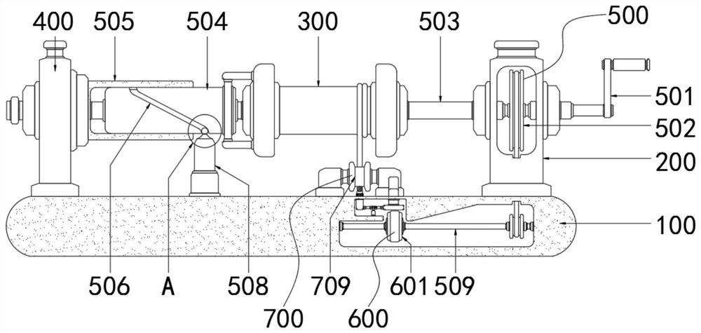
[0022] see figure 1 , a wire coil winding machine, including a base 100, an inner cavity column 200, a reel 300, a support column 400, a wire take-up assembly 500, a centrifugal assembly 600 and a tensioning assembly 700, the top of the base 100 and the inner cavity column 200 Fixed connection, the left side of the inner wall of the inner cavity column 200 is movably connected with the take-up assembly 500, the outer wall of the take-up assembly 500 is movably...


PUM


Abstract

The invention relates to the technical field of electric power, and discloses a wire coiling and winding take-up machine which comprises a base, an inner cavity column, a winding drum, a supporting column, a take-up assembly, a centrifugal assembly and a tensioning assembly, wherein the top end of the base is fixedly connected with the inner cavity column, the left side of the inner wall of the inner cavity column is movably connected with the take-up assembly, the outer wall of the take-up assembly is movably connected with the winding drum, the top end of the base is located on the left side of the take-up assembly and fixedly connected with the supporting column, the bottom end of the take-up assembly is movably connected with the centrifugal assembly, and the top end of the inner wall of the base is located above the centrifugal assembly and movably connected with the tensioning assembly. According to the wire coiling and winding take-up machine, a crank is rotated to drive a transmission shaft to move, the transmission shaft drives the inner column to rotate, the inner column drives a winding drum to move left and right on the transmission shaft in a reciprocating mode through a snakelike groove and a rolling ball, so that an electric wire winds on the winding drum neatly and evenly, and the electric wire needed to be used can be rapidly unfolded, and a situation that the electric wires are wound together is avoided.

Description

technical field [0001] The invention relates to the technical field of electric power, in particular to a coil winding and take-up machine for electric wires. Background technique [0002] In agricultural production, it is often necessary to use water pumps to irrigate the farmland or use devices such as conveyor belts to transport seedlings. These devices require power to start, so in the farmland, electrical equipment is often used to connect electrical equipment to remote power sources. Together, since the farmland is often tens or hundreds of acres together, so is the length of the wires required. After the wires are used, they are usually coiled together manually for the next use, but when coiling the wires Due to the length of the wires, it will be extremely inconvenient to use the wires next time. This is because the wires are all entangled together, and the winding positions are often messy. Causes damage to the wires, making it take a long time to organize the wire...

Claims


Application Information

Patent Timeline
Patent Type & Authority Applications(China)
IPC IPC(8): B65H54/28B65H54/553B65H54/70B65H59/10
CPCB65H54/2803B65H54/553B65H54/70B65H59/10B65H2701/34
Inventor 王文
Owner 王文
Why Eureka
Try Eureka