
Sludge separation pump and using method thereof

A technology for separating pumps and sludge, applied in separation methods, filtration separation, chemical instruments and methods, etc., can solve the problems of inconvenient disassembly of anti-blocking covers, affecting the working efficiency of anti-blocking sludge pumps, polluting water bodies, etc.

Pending Publication Date: 2021-05-18
SINOHYDRO BUREAU 7 CO LTD
View PDF0 Cites 1 Cited by
  • Summary
  • Abstract
  • Description
  • Claims
  • Application Information

AI Technical Summary

Problems solved by technology

[0002] Sludge cleaning has always been a big problem. Sludge contains a lot of water. If it is directly dried in the sun, the cycle will be very long, and it will easily cause the odor to spread. When pumping the water, it is easy to block the pump.
[0003] The common thing that needs to be cleaned of silt is the underwater box culvert, which contains silt, domestic garbage, dead leaves and residual limbs, etc., and is easy to deposit during the flow of water, so that the box culvert deposits a large amount of silt and the above attachments, which not only affects The normal flow of the underwater box culvert, and the reaction of a large number of anaerobic bacteria in the sludge will pollute the water body and produce peculiar smell, which will have a great impact on people's living environment
[0004] During the treatment process, a sludge pump is required to carry out dredging operations to pump out the sludge and improve the water body. Since the sludge contains various sundries, anti-blocking type sludge pumps with anti-blocking covers are often used to block the sundries and place them. However, the anti-blocking type sludge pump currently used is easy to cover the entrance of the anti-blocking cover with debris, blocking the flow channel, affecting the normal pumping of the sludge, and affecting the operating efficiency of the anti-blocking type sludge pump. It is inconvenient to disassemble the anti-blocking cover, and it is obviously difficult to quickly disassemble and clean the anti-blocking cover at the dredging site

Method used

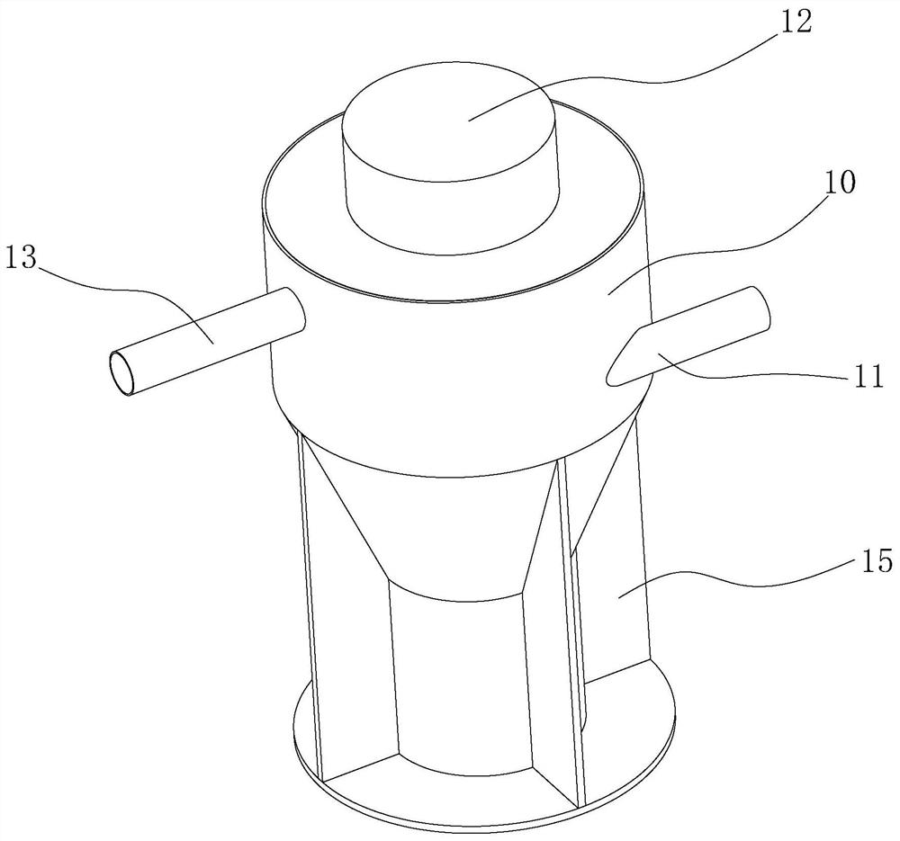
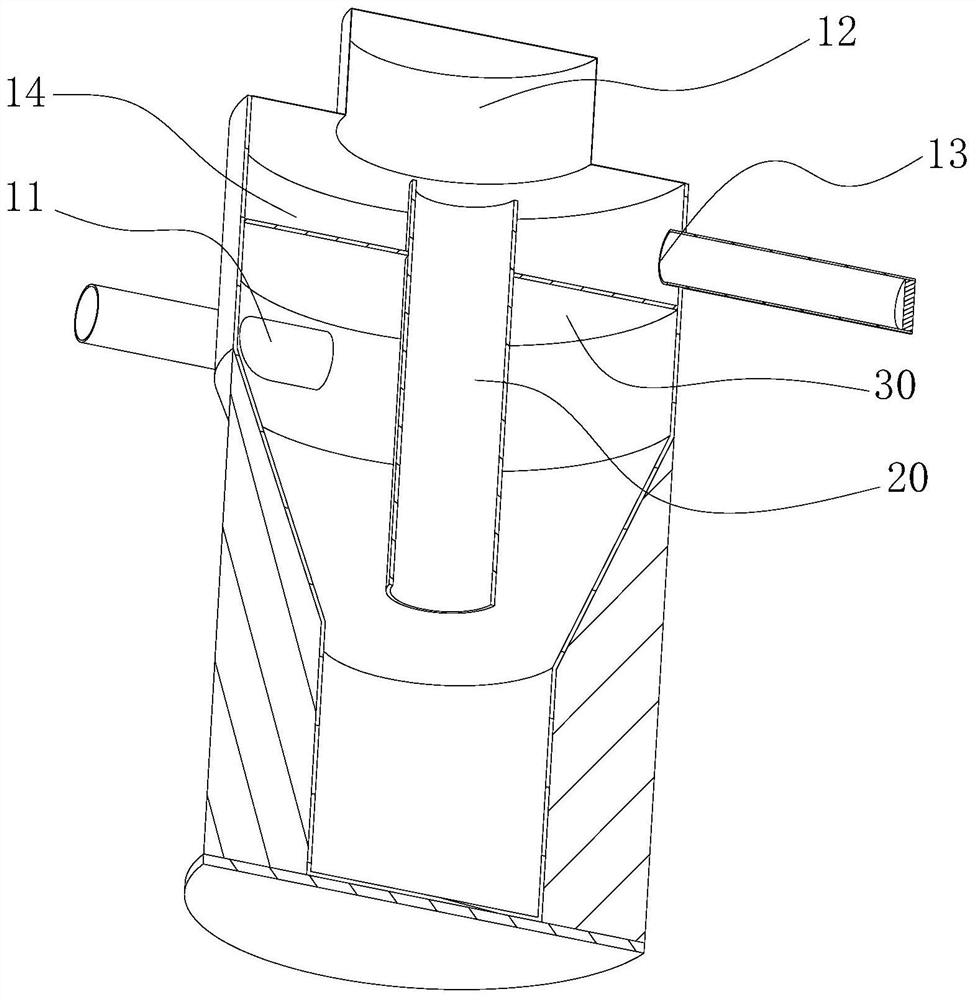
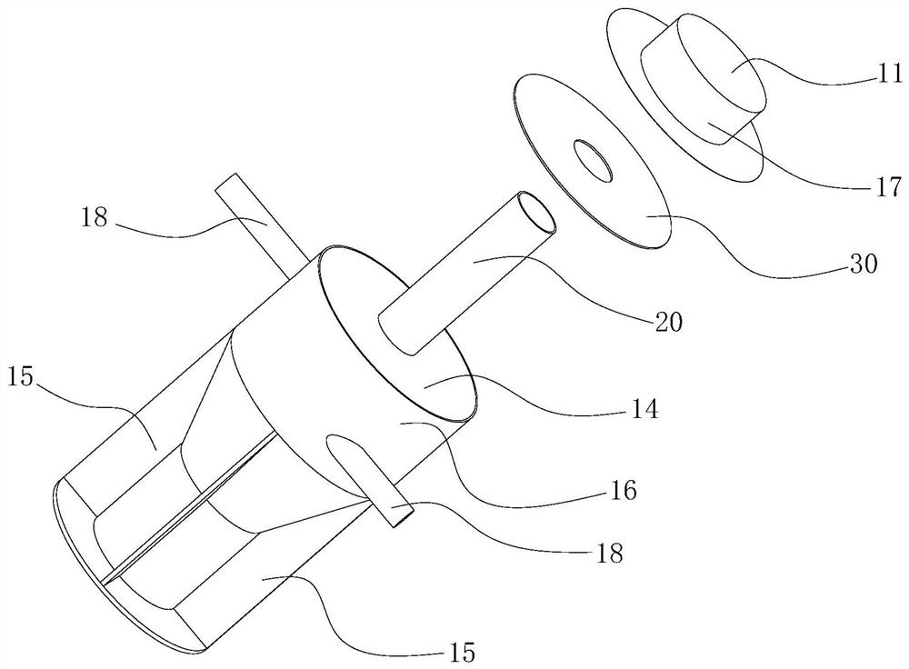

Image

  • Sludge separation pump and using method thereof
  • Sludge separation pump and using method thereof
  • Sludge separation pump and using method thereof

Examples


Embodiment Construction

[0031] In order to facilitate understanding of the present invention, specific embodiments of the present invention will be described in more detail below with reference to the accompanying drawings.

[0032] Unless specified otherwise or defined otherwise, all technical and scientific terms used herein have the same meaning as commonly understood by one of ordinary skill in the art. In the case of combining the technical solution of the present invention with a real scene, all technical and scientific terms used herein may also have meanings corresponding to the purpose of realizing the technical solution of the present invention.

[0033] Unless otherwise specified or otherwise defined, "first, second..." used herein is only used to distinguish names, and does not represent a specific quantity or order.

[0034] Unless specifically stated or defined otherwise, as used herein, the term "and / or" includes any and all combinations of one or more of the associated listed items. ...


PUM


Abstract

The invention belongs to the field of sludge cleaning, and discloses a sludge separation pump and a using method thereof. The sludge separation pump comprises an outer shell, a motor and a filter disc, the outer shell is provided with a liquid inlet, a first discharge port, a second discharge port and an internal containing cavity, the liquid inlet, the first discharge port and the second discharge port all communicate with the containing cavity, the filter disc is installed in the containing cavity, the containing cavity is divided into a first cavity area and a second cavity area, an output shaft of the motor is connected with the filter disc, the liquid inlet and the first discharging opening are located in the first cavity area, and the second discharging opening is located in the second cavity area. By rotating the filter disc, the separation of sludge and water is realized by utilizing the filtering effect and the centrifugal effect.

Description

technical field [0001] The invention belongs to the field of sludge cleaning, in particular to a sludge separation pump and its application method. Background technique [0002] Sludge cleaning has always been a big problem. Sludge contains a lot of water. If it is directly dried in the sun, the cycle will be very long, and it will easily cause the odor to spread. When the water is pumped, it is easy to block the pump. [0003] The common thing that needs to be cleaned of silt is the underwater box culvert, which contains silt, domestic garbage, dead leaves and residual limbs, etc., and is easy to deposit during the flow of water, so that the box culvert deposits a large amount of silt and the above attachments, which not only affects The normal flow of the underwater box culvert and the reaction of a large number of anaerobic bacteria in the sludge will pollute the water body and produce peculiar smell, which will have a great impact on people's living environment. [0004...

Claims


Application Information

Patent Timeline
IPC IPC(8): C02F11/121C02F11/127B01D35/02B01D33/17B01D33/80
CPCC02F11/121C02F11/127B01D35/02B01D33/17B01D33/80
Inventor 郭昆鹏唐孝林汤家源赵银江孙虹波柴俊孙肇坤王晓宇
Owner SINOHYDRO BUREAU 7 CO LTD
Learn More