Finite element sub-model boundary condition loading method

A technology of boundary conditions and sub-models, applied in instrumentation, geometric CAD, design optimization/simulation, etc., can solve problems such as inability to achieve 2D-3D conversion, inaccurate boundary conditions, etc.

Active Publication Date: 2021-05-18
BEIJING INSTITUTE OF TECHNOLOGYGY
View PDF4 Cites 0 Cited by
  • Summary
  • Abstract
  • Description
  • Claims
  • Application Information

AI Technical Summary

Problems solved by technology

[0004] Aiming at the problem that the boundary conditions of the traditional sub-model loading method are inaccurate and cannot realize the transformation from 2D to 3D, the present invention proposes a finite element sub-model boundary condition loading method, by extracting the node coordinates of the overall model, using coordinate transformation and nonlinear fitting The method realizes the sub-model boundary condition loading under the large deformation gradient, and realizes the mutual transformation between the 3D model and the 2D model

Method used


Image

  • Finite element sub-model boundary condition loading method
  • Finite element sub-model boundary condition loading method
  • Finite element sub-model boundary condition loading method

Examples


Embodiment 1

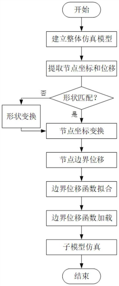
[0049] Such as figure 1 As shown, applying a finite element sub-model boundary condition loading method of the present invention, the finite element simulation analysis of torsion fatigue test is carried out to the torsion shaft, including the following steps:

[0050] Step 1. Overall model modeling and simulation:

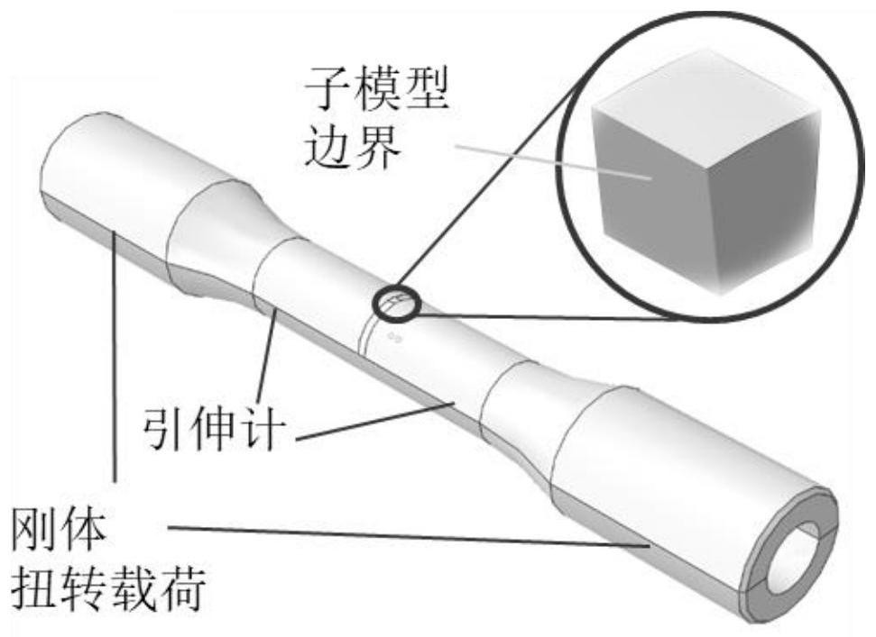
[0051] The torsion axis is a hollow tubular sample made of 45CrNiMoVA material. The fatigue load is controlled by strain, with a maximum strain of 2.4%. Based on the shape of the torsion axis and the stress loading method, an overall model of the workpiece is established. Nodes are arranged on the surface of the middle section of the model and corresponding sets are established, and torsional loads are applied to the overall model, and the overall model is submitted for finite element simulation to obtain the deformation of the overall model.

[0052] The equal-scale finite element simulation model of the workpiece and the sub-model boundaries such as figure 2 ...

Embodiment 2

[0086] Apply a kind of finite element sub-model boundary condition loading method of the present invention, carry out the finite element simulation analysis of two-dimensional tensile fatigue test to workpiece, comprise the following steps:

[0087] Step 1. Overall model modeling and simulation:

[0088] Based on the shape of the workpiece and the stress loading method, the overall model of the workpiece is established; according to the needs of sub-model modeling, the nodes are arranged in the middle of the overall model specimen size and the corresponding collection is established; The tensile fatigue test method is used to load the overall model with tensile load; the overall model is submitted for finite element simulation to obtain the deformation of the overall model. The finite element simulation results of the overall model are as follows: Figure 9 shown.

[0089] Step 2. Extract the coordinates and displacements of the boundary nodes of the overall model:

[0090] ...


PUM


Abstract

The invention discloses a finite element sub-model boundary condition loading method, and belongs to the technical field of finite element simulation. According to the finite element sub-model boundary condition loading method, by extracting overall model node coordinates and adopting coordinate transformation and nonlinear fitting modes, sub-model boundary condition loading under a large deformation gradient is achieved, and mutual transformation between a three-dimensional model and a two-dimensional model is achieved. According to the method, node displacement extracted from the whole model is fitted by adopting a nonlinear fitting method, and is loaded to the sub-model as a boundary condition, so that the established boundary condition is more accurate and reliable, and finite element simulation errors can be greatly reduced; according to the method, the node displacement is extracted by adopting an external script, and the node displacement on the whole model is converted by adopting a coordinate conversion method, so that sub-model loading of different dimensions and different unit types can be realized, the application range of a finite element sub-model method is greatly expanded, and the method has wide application value.

Description

technical field [0001] The patent of the present invention relates to a method for loading boundary conditions of a finite element sub-model, in particular to a method for loading boundary conditions of a sub-model for nonlinear boundaries, and belongs to the technical field of finite element simulation. Background technique [0002] With the development of simulation technology, more and more engineering problems need to be solved by referring to the results obtained by finite element method simulation. The accuracy of finite element simulation results has a huge impact on practical engineering problems. In order to reflect the actual problems, it is often necessary to establish a simulation model with the same proportion as the actual workpiece. The structure of the real workpiece is complex and the size is large, and a large number of finite element meshes are often required for simulation. At the same time, it is difficult to focus on local problems in the simulation mod...

Claims


Application Information

Patent Timeline
Patent Type & Authority Applications(China)
IPC IPC(8): G06F30/17G06F30/23G06F119/14
CPCG06F30/17G06F30/23G06F2119/14
Inventor 解丽静高飞农郭智昊王泽诚刘桐语邱波王西彬
Owner BEIJING INSTITUTE OF TECHNOLOGYGY
Why Eureka
Try Eureka