Radiating unit, antenna and base station

A technology of radiating elements and radiating lines, applied in the structural form of radiating elements, antennas, resonant antennas, etc., can solve the problems of restricting the performance of base station antennas, coupling interference, etc.

Active Publication Date: 2021-05-18
COMBA TELECOM TECH (GUANGZHOU) CO LTD +1
View PDF7 Cites 10 Cited by
  • Summary
  • Abstract
  • Description
  • Claims
  • Application Information

AI Technical Summary

Problems solved by technology

[0003] The base station antenna includes radiation units of multiple frequency bands, and the radiation units of multiple frequency bands will couple and interfere with each other, especially the low frequency radiation unit will interfere with the high frequency radiation unit It will cause more serious coupling interference, especially the impact on the pattern index, which seriously restricts the performance of the base station antenna

Method used


Image

  • Radiating unit, antenna and base station
  • Radiating unit, antenna and base station
  • Radiating unit, antenna and base station

Examples


Embodiment 1

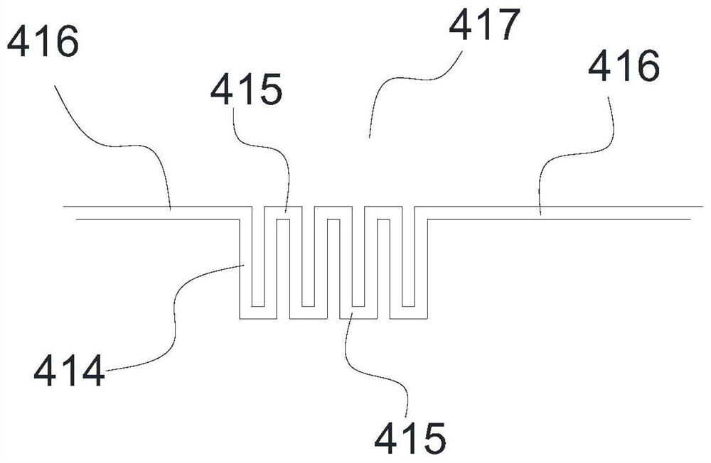
[0073] Embodiment one, see image 3 , each extension branch 414 of the filter unit is arranged perpendicular to the extension direction of the connection line 416, the same end of the connection line 416 and all extension branches 414 of the filter unit are located on the same axis, and the transition branch 415 connecting the extension branches 414 is in the form of a straight line , thus forming a square-wave filter unit, and the filter unit 413 is called a square-wave filter unit 417 .

[0074] In a transformation implementation based on Example 1, see Image 6 , the connecting line 416 is located on the same axis as the central axis in the extension direction of all the extension branches 414 of the filter unit, and this filter unit is called a square wave filter unit 418 .

Embodiment 2

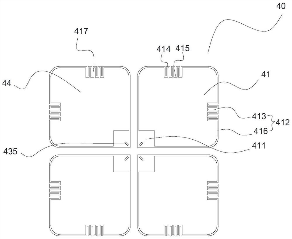
[0075] Embodiment two, see Figure 4 , each extension branch 414 of the filter unit is arranged perpendicular to the extension direction of the connection line 416, the same end of the connection line 416 and all extension branches 414 of the filter unit are located on the same axis, and the transition branch 415 connecting the extension branches 414 is an arc segment form, thereby forming a wave-shaped filter unit, which is called a wave filter unit 419 .

Embodiment 3

[0076] Embodiment three, see Figure 5 Each extension branch 414 of the filter unit is arranged obliquely with respect to the extension direction of the connection line 416. Specifically, the extension branch 414 and the extension direction of the connection line 416 form an angle of 60 or 120 degrees. The connection line 416 and all extension branches 414 of the filter unit The same end is located on the same axis, and the transition branch 415 connecting the extension branch 414 is in the form of a straight line segment, forming a rhombic wave filter unit, which is called a rhombic square wave filter unit 420 .


PUM


Abstract

The invention provides a radiation unit, an antenna and a base station, the radiation unit comprises two dipoles which are arranged in a polarization orthogonality mode, each dipole comprises two opposite radiation arms, the radiation arms are arranged in a surrounding mode so as to feed around a central area of each other, each radiation arm comprises a feed part and a radiation line, each feed part is formed at the position, corresponding to the central area, of the corresponding radiation arm, each radiation line comprises a linear body and at least one filtering unit, the bodies and the feed parts are connected to form a closed-loop structure, and the filtering unit is formed by bending the body in a reciprocating mode. According to the radiation unit, the filtering units are arranged on the two radiation arms of the dipoles and used for filtering high-frequency harmonic waves, and the problem of mutual coupling caused by the fact that the distance between the radiation units is small is solved.

Description

technical field [0001] The present invention relates to the technical field of mobile communication, in particular to a radiation unit, an antenna configured with the radiation unit, and a base station configured with the antenna. Background technique [0002] As 5G communication technology continues to be put into commercial use, the frequency bands and number of radiation units required in base stations have greatly increased. Miniaturized, multi-band and multi-standard base station antennas have increasingly become mainstream antennas used in the communication industry. [0003] The base station antenna includes radiating units of multiple frequency bands, and the radiating units of multiple frequency bands will couple and interfere with each other, especially the low-frequency radiating units will cause serious coupling interference to the high-frequency radiating units, especially for the pattern index. These problems seriously restrict the performance of the base stati...

Claims


Application Information

Patent Timeline
Patent Type & Authority Applications(China)
IPC IPC(8): H01Q1/36H01Q1/50H01Q9/16H01Q1/52H01Q21/24H01Q21/00H01Q21/30H01Q19/10H01Q1/24
CPCH01Q1/36H01Q1/50H01Q9/16H01Q1/521H01Q21/24H01Q21/0006H01Q21/30H01Q19/10H01Q1/246
Inventor 姜维维成阳黄立文黄文铿
Owner COMBA TELECOM TECH (GUANGZHOU) CO LTD
Why Eureka
Try Eureka