Automatic fiber laying variable-angle path planning method for non-developable curved surface part

A curved surface part and fiber laying technology, which is applied in the field of fiber laying trajectory planning for non-developable curved surface parts, can solve the problems affecting the shape accuracy of composite material components, the impact of various performances, and the complexity of the fiber laying process.

Active Publication Date: 2012-07-04
HARBIN INST OF TECH
View PDF4 Cites 24 Cited by
  • Summary
  • Abstract
  • Description
  • Claims
  • Application Information

AI Technical Summary

Problems solved by technology

[0003] The purpose of the present invention is to solve the inevitable phenomenon of shearing and re-feeding of non-developable curved surface parts in the process of automatic fiber laying, which affects the shape accuracy of composite material components and affects various performances, so that fiber laying To solve the problem of increased complexity of the process, a method for automatic fiber placement variable angle trajectory planning for non-developable curved parts is provided

Method used


Image

  • Automatic fiber laying variable-angle path planning method for non-developable curved surface part
  • Automatic fiber laying variable-angle path planning method for non-developable curved surface part
  • Automatic fiber laying variable-angle path planning method for non-developable curved surface part

Examples


specific Embodiment approach 1

[0101] Specific implementation mode one: combine figure 1 , Figure 4 , Figure 5 , Figure 8 ~ Figure 10 , Figure 15 and Figure 16 Explain, the non-developable curved surface parts automatic fiber laying variable angle trajectory planning method of this embodiment, the method is implemented by the following steps:

[0102] Step 1: Obtain data information of non-developable surface parts;

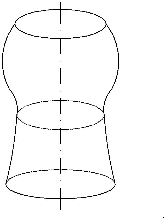
[0103] The non-extensible curved surface part is a non-extensible rotary cylindrical part (such as a device casing), the axis of the non-extensible rotary cylindrical part is a straight line, and the cross-sections perpendicular to the axis are all circular sections, and the non-extensible rotary cylindrical part is a circular section. The generatrices of rotary cylinder parts are spline curves;

[0104] Divide the axis into m-1 parts (equal division principle: the spacing should be greater than the motion accuracy of the laying equipment, and at the same time be less than the accur...

specific Embodiment approach 2

[0135] Specific implementation mode two: combination figure 2 , Figure 6 , Figure 11 , Figure 12 , Figure 15 and Figure 16 Explain, the non-developable curved surface parts automatic fiber laying variable angle trajectory planning method of this embodiment, the method is implemented by the following steps:

[0136] Step 1: Obtain data information of non-developable surface parts;

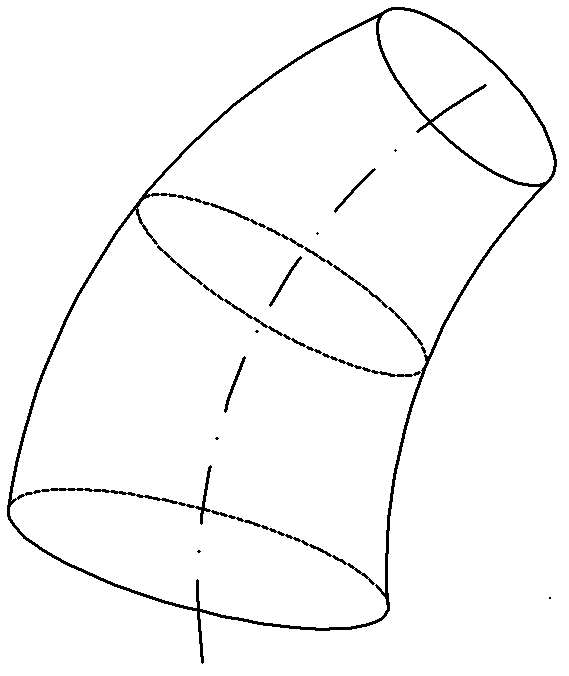
[0137] The non-developable curved surface part is a non-developable curved surface variable-section conical shell part, the axis of the non-developable curved surface variable-section conical shell part is a curve, and the sections perpendicular to the axis are all circular sections, and the circular section The size of the perimeter changes continuously, and the circular section with the smallest perimeter appears on one end of the non-developable surface variable-section conical shell part;

[0138] Divide the axis into m-1 parts (equal division principle: the spacing should be greater...

specific Embodiment approach 3

[0160] Specific implementation mode three: combination image 3 , Figure 7 and Figure 13 to Figure 16 Explain, the non-developable curved surface parts automatic fiber laying variable angle trajectory planning method of this embodiment, the method is implemented by the following steps:

[0161] Step 1: Obtain data information of non-developable surface parts;

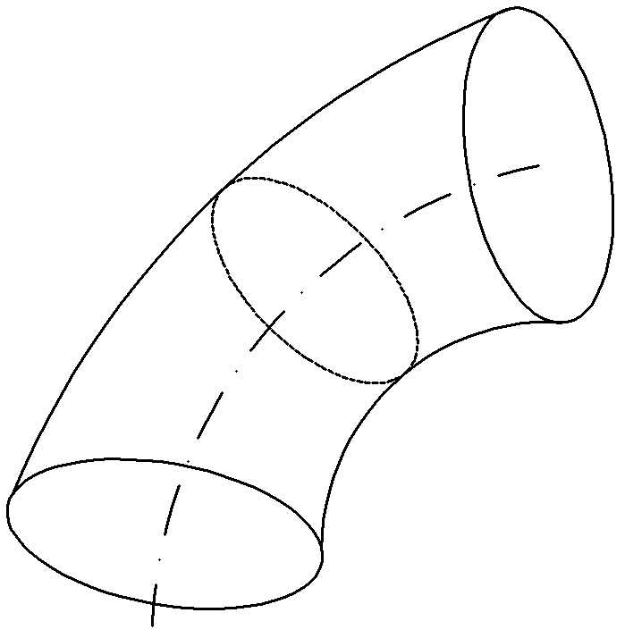
[0162] The non-developable curved surface part is a non-developable curved surface variable-section joint type part, the axis of the non-developable curved surface variable-section joint type part is a curve, and the sections perpendicular to the axis are all circular sections, and the circumference of the circular section is The size of is continuously changing, and the circular section with the smallest circumference appears in the middle of the non-developable surface variable section joint parts;

[0163] Divide the axis into m-1 parts (equal division principle: the spacing should be greater than the motion acc...


PUM


Abstract

The invention discloses an automatic fiber laying variable-angle path planning method for a non-developable curved surface part, which relates to a fiber laying path plan making method for a non-developable curved surface part and is used for solving the problem that in the complexity of a fiber laying process, the appearance accuracy and various properties of a composite material are influenced by inevitable shearing and re-conveying phenomena occurring in the automatic fiber laying process of the non-developable curved surface part. In a scheme I, the method comprises the following steps of: acquiring data information from a non-developable revolving barrel part; calculating the laying reference angle of a presoaked tow on each intersection line; determining points on an initial path; determining points on other paths; and making a path line. A scheme II is different from the scheme I in that data information is acquired from a non-developable curved surface variable-section conical shell part; and a scheme III is different from the scheme I and the scheme II in that data information is acquired from a non-developable curved surface variable-section joint part. The method is used for planning an automatic fiber laying variable-angle path on the outer surface of the non-developable curved surface part.

Description

technical field [0001] The invention relates to a method for planning a fiber laying trajectory of a non-developable curved surface part. Background technique [0002] Automatic lay-up technology is one of the advanced manufacturing technologies to realize the molding of large-size and complex-shaped composite components. In the automatic fiber placement process, the trajectory planning algorithm adopted will directly affect the performance of the final composite component and the complexity of the placement process. At present, in actual production, the most commonly used method is to manufacture 0° layups, 45° layups and 90° layups by laying at a fixed angle. Researchers from Delft University of Technology in the Netherlands proposed "variable stiffness" ply laying. The change of the stiffness of this kind of ply is caused by the continuous change of laying angle. For variable angle laying, they studied the measured Trajectory planning algorithms for ground line, constan...

Claims


Application Information

Patent Timeline
Patent Type & Authority Applications(China)
IPC IPC(8): B29C70/38
Inventor 韩振宇李玥华富宏亚
Owner HARBIN INST OF TECH
Why Eureka
Try Eureka