
Power distribution cabinet with mechanical trigger switch

A trigger switch and power distribution cabinet technology, which is applied in the cooling/ventilation of substation/switchgear, details of substation/switch layout, electrical components, etc. It can solve problems such as labor-intensive and internal circuit fires in power distribution cabinets

Inactive Publication Date: 2021-05-18
SHANGHAI PEOPLE ELECTRICAL APPLIANCE GROUP
View PDF0 Cites 0 Cited by
  • Summary
  • Abstract
  • Description
  • Claims
  • Application Information

AI Technical Summary

Problems solved by technology

[0003] Most of the existing power distribution cabinets use the method of manually monitoring the internal temperature of the power distribution cabinet, and manually controlling the heat dissipation mechanism to dissipate heat from the power distribution cabinet, which consumes a lot of manual energy, and once the operation is not timely, it is easy to cause damage to the internal circuit of the power distribution cabinet. Phenomenon of fire

Method used


Image

  • Power distribution cabinet with mechanical trigger switch
  • Power distribution cabinet with mechanical trigger switch
  • Power distribution cabinet with mechanical trigger switch

Examples


Embodiment Construction

[0025] The following will clearly and completely describe the technical solutions in the embodiments of the present invention with reference to the accompanying drawings in the embodiments of the present invention. Obviously, the described embodiments are only some, not all, embodiments of the present invention. Based on the embodiments of the present invention, all other embodiments obtained by persons of ordinary skill in the art without creative work fall within the protection scope of the present invention. The present invention will be further described below in conjunction with the embodiments.

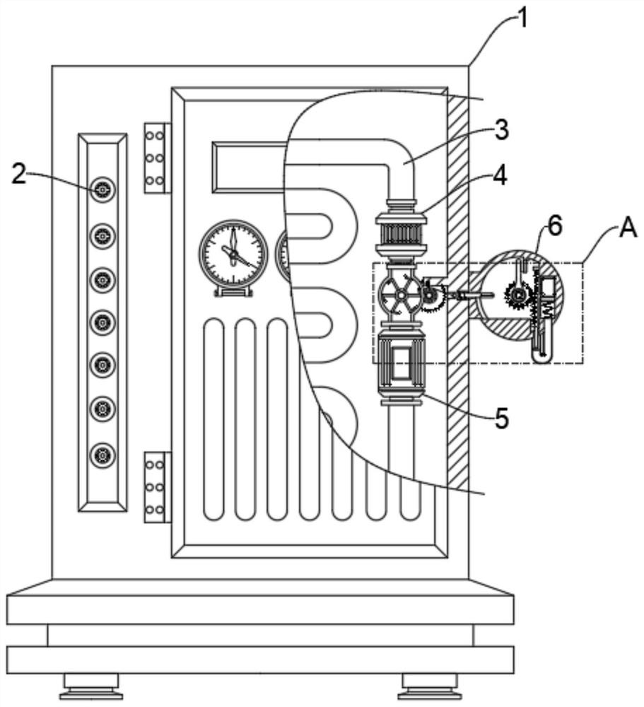
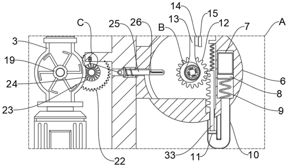
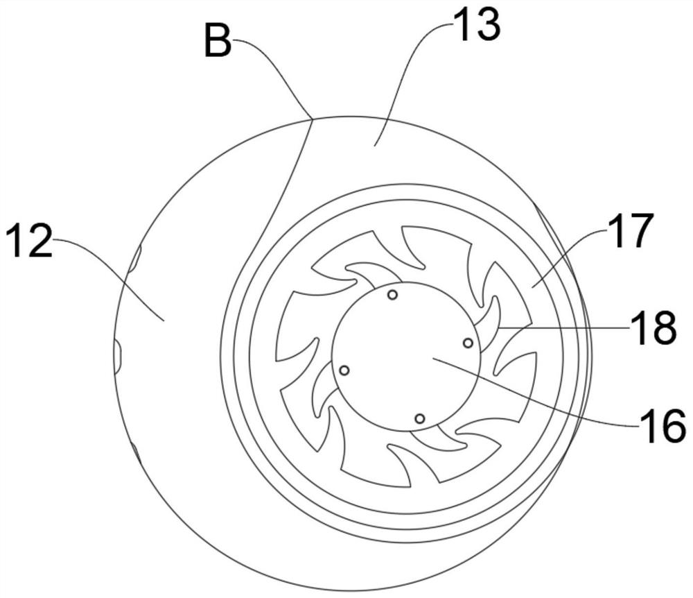
[0026] see Figure 1-4 , in an embodiment of the present invention, a power distribution cabinet with a mechanical trigger switch, including a power distribution cabinet 1, a plurality of terminal blocks 2 are equidistantly arranged on the power distribution cabinet 1, and the power distribution cabinet 1 1 is equipped with a water-cooled heat dissipation assembly, the water-coo...


PUM


Abstract

The invention relates to the technical field of power distribution cabinets, in particular to a power distribution cabinet with a mechanical trigger switch. The power distribution cabinet comprises a power distribution cabinet body, a plurality of connector lugs are arranged on the power distribution cabinet body at equal intervals, and a water-cooling heat dissipation assembly is arranged in the power distribution cabinet body and comprises a heat dissipation mechanism and the mechanical trigger mechanism. The heat dissipation mechanism comprises a liquid cooling pipe, a condenser and a water pump, the liquid cooling pipe, the condenser and the water pump are all fixedly installed in the power distribution cabinet body, and the water pump and the condenser are connected through the liquid cooling pipe. According to the whole device, the temperature change in the power distribution cabinet body is monitored in real time, when the temperature reaches a certain value, the heat dissipation mechanism is automatically triggered through a linked mechanical structure to carry out liquid cooling heat dissipation work on the power distribution cabinet body, the traditional mode of manual monitoring and manual control of the heat dissipation mechanism is eliminated, the labor force is reduced, and the practicability is higher.

Description

technical field [0001] The invention relates to the technical field of power distribution cabinets, in particular to a power distribution cabinet with a mechanical trigger switch. Background technique [0002] The power distribution cabinet is the general name of the motor control center. The power distribution cabinet is used in the occasions where the load is relatively scattered and there are few circuits; the motor control center is used in the occasions where the load is concentrated and there are many circuits. The electric energy is distributed to the nearest loads. [0003] Most of the existing power distribution cabinets use the method of manually monitoring the internal temperature of the power distribution cabinet, and manually controlling the heat dissipation mechanism to dissipate heat from the power distribution cabinet, which consumes a lot of manual energy, and once the operation is not timely, it is easy to cause damage to the internal circuit of the power d...

Claims


Application Information

Patent Timeline
IPC IPC(8): H02B1/32H02B1/56
CPCH02B1/32H02B1/565
Inventor 黄山郑纬鸿潘长春潘小强
Owner SHANGHAI PEOPLE ELECTRICAL APPLIANCE GROUP
Learn More