Ultrasonic imaging device, treatment support system, and image processing method
A camera device, ultrasonic technology, applied in ultrasonic/sonic/infrasound equipment control, ultrasonic/sonic/infrasonic diagnosis, sonic diagnosis, etc., can solve the problem that the front end of the guide wire is not easy and has not yet reached popularization.
- Summary
- Abstract
- Description
- Claims
- Application Information
AI Technical Summary
Problems solved by technology
Method used
Image
Examples
no. 1 approach
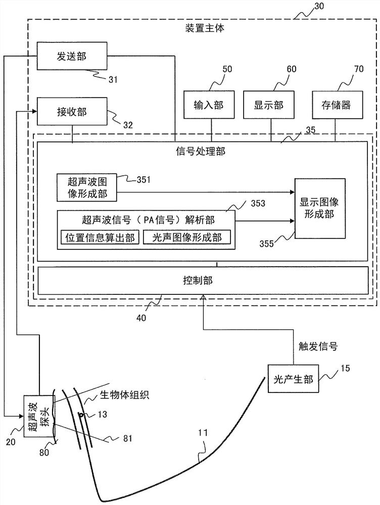
[0057] In the present embodiment, the analyzing unit 353 estimates the distance in the lateral direction of the ultrasonic generating source 13 using the time difference between the arrival times of the ultrasonic waves (beacon ultrasonic signals) from the ultrasonic generating source 13 detected by the elements of the 1D array probe 20A. . In this embodiment, the case where the ultrasonic waves emitted by the ultrasonic wave generation source 13 are PA signals is also described as an example.
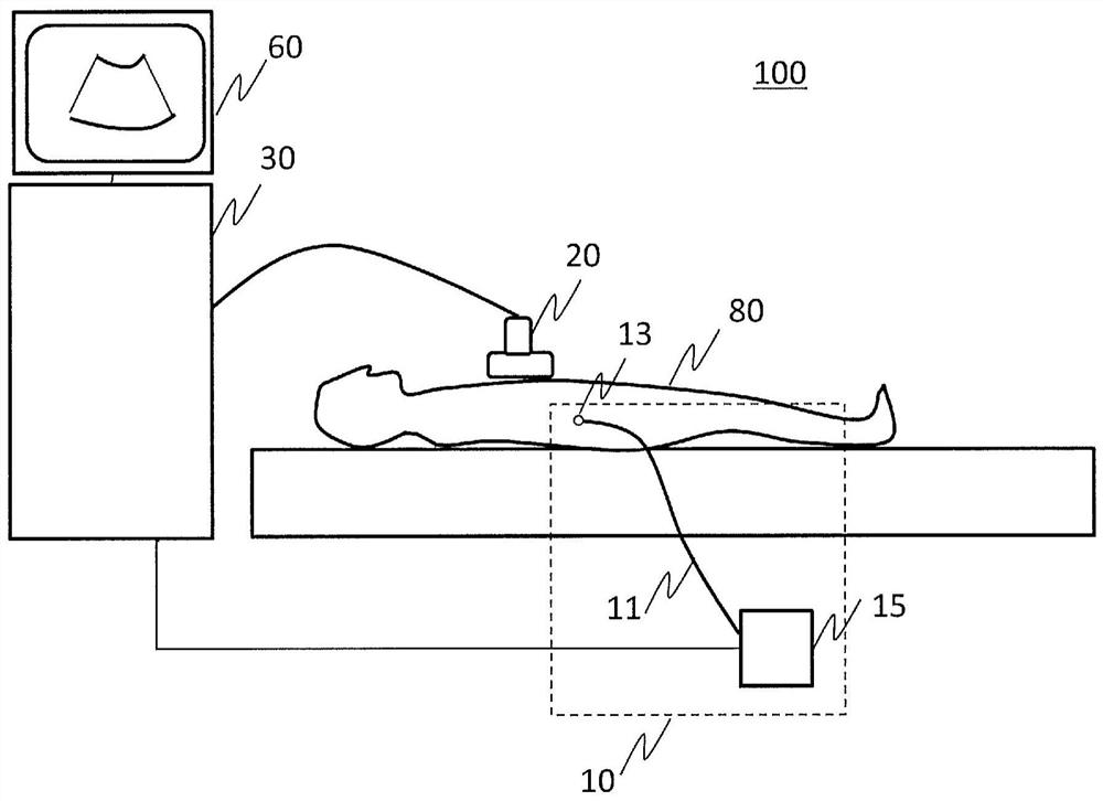
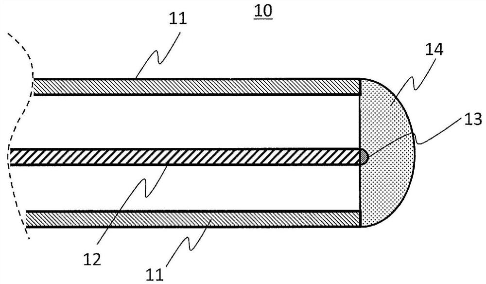
[0058] Such as Figure 5 As shown, when the guide wire 11 is inserted into the blood vessel (80A) and pushed toward the treatment site (target), if the plane along the blood vessel is taken as an imaging cross-section, the guide wire will be taken from the left and right sides of the imaging area. Travel in either direction to the camera area. Therefore, by estimating the distance in the lateral direction, it is possible to know to what extent the guide wire is approaching the target...
no. 2 approach
[0085] In the first embodiment and its modified example, the position (distance in the lateral direction) of the PA signal generation source 13 is estimated by using the time difference of the PA signal reaching each element of the ultrasonic probe, but the analyzing unit 353 of the present embodiment estimates the PA signal A three-dimensional position of the source 13 is generated. It is presumed that there are methods in which a three-dimensional position can be grasped by operating the 1D ultrasound probe 20A (first technique), and a technique in which an ultrasound probe 20B capable of grasping a three-dimensional position is used (second technique). In any case, the same technique as that of the first embodiment is employed for the lateral direction. First, the first method will be described.
[0086] [first approach]
[0087] Figure 8 It is a figure which shows the flow of the process of a 1st method. As shown in the figure, in this embodiment, as in the first embo...
no. 3 approach
[0098] In the first embodiment and the second embodiment, the analysis unit 353 estimates the position of the ultrasonic generation source using the difference between the elements (arrival time difference) of the time when the ultrasonic wave from the ultrasonic generation source reaches the ultrasonic probe, but in the present embodiment , the distance is estimated using the features of the image generated in the beacon ultrasonic image (PA image) corresponding to the time difference of arrival, specifically, using split. That is, in the ultrasonic imaging device according to the present embodiment, the ultrasonic image forming unit 351 has a function of forming an image of an ultrasonic source by using a beacon ultrasonic signal, and the analyzing unit 353 uses the image of the ultrasonic source generated by the ultrasonic image forming unit 351 to information to estimate the position of the ultrasonic generator 13.
[0099]The influence of the time difference of arrival oc...
PUM
 Abstract
Description
Claims
Application Information
 - R&D
- Intellectual Property
- Life Sciences
- Materials
- Tech Scout
- Unparalleled Data Quality
- Higher Quality Content
- 60% Fewer Hallucinations
Browse by: Latest US Patents, China's latest patents, Technical Efficacy Thesaurus, Application Domain, Technology Topic, Popular Technical Reports.
© 2025 PatSnap. All rights reserved.Legal|Privacy policy|Modern Slavery Act Transparency Statement|Sitemap|About US| Contact US: help@patsnap.com


