Rollable annular frame type hole digging device with sliding grooves

A rolling ring and chute technology, which is applied in the field of a rolling ring frame type burrowing device, can solve the problems of inconvenient practical application, heavy equipment, and large artificial physical strength consumption, and achieves compact overall structure, flexible and convenient use, and easy portability. Effect

Pending Publication Date: 2021-05-25
黄兵
View PDF0 Cites 0 Cited by
  • Summary
  • Abstract
  • Description
  • Claims
  • Application Information

AI Technical Summary

Problems solved by technology

[0002] In the process of mountain afforestation, due to the limitation of mountain terrain, artificial shovels are often used in the process of digging holes, which consumes a lot of manual energy; the existing hand-held digging equipment can be used in mountainous areas, and the structure uses a spiral head to dig holes. The main problems encountered in the practical application of this kind of equipment are: if the holes that meet the requirements are punched at one time, the spiral blades used in the existing hole-digging equipment have a large outer diameter, and the whole equipment is heavy, which is not conducive to mountain towing; The existing hole digging equipment with small size is limited by the structure of the spiral blade during the hole expansion process, and the staff cannot keep the equipment stable. The hole expansion operation is difficult and inconvenient for practical application

Method used


Image

  • Rollable annular frame type hole digging device with sliding grooves

Examples


Embodiment Construction

[0014] Below in conjunction with embodiment the specific embodiment of the present invention is described in further detail:

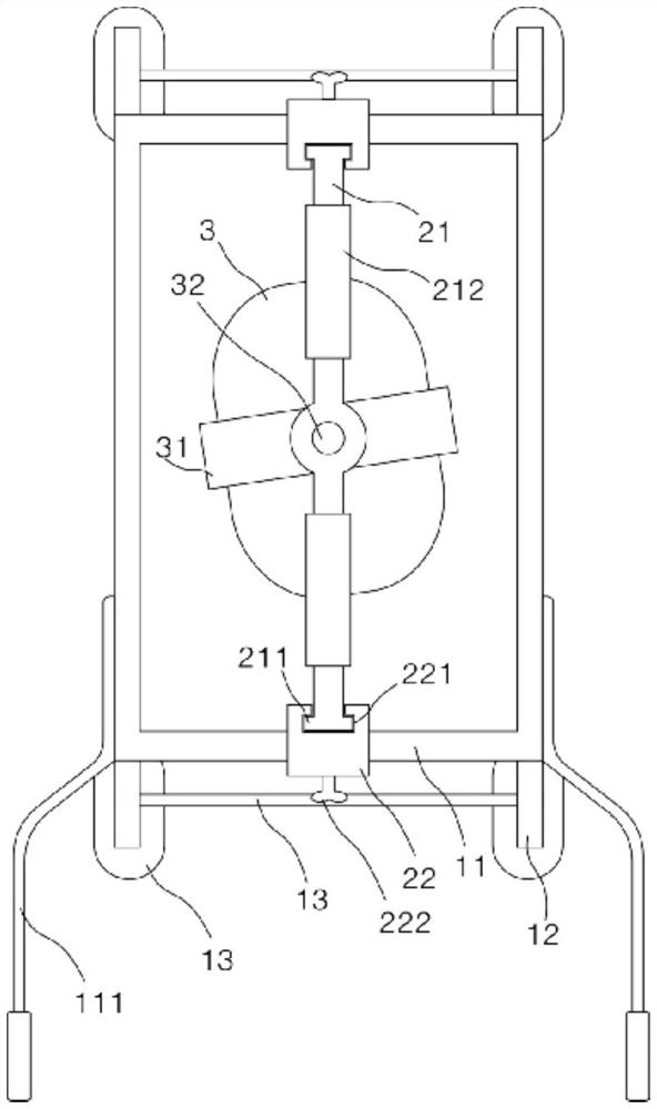
[0015] Such as figure 1 As shown, an embodiment of a rollable ring frame type hole digging device with a chute includes a rectangular frame and an excavating device arranged in the middle of the rectangular frame. The rectangular frame includes: an installation frame 11, and an The legs 12 are provided with wheels 121, the rear of the installation frame 11 is equipped with an armrest 111, the legs 12 are inclined 10 degrees to the outside, and a connecting plate 13 is arranged between the two legs 12 on the front and rear sides, and the connecting plate 13 It is arranged horizontally with the installation frame 11, and a corner plate is connected between the connecting plate 13 and the legs 12, and the corner plate forms a triangular support structure with the connecting plate 13 and the legs 12; The support rod 31 and the shaft handle 32, the two end...


PUM


Abstract

The invention discloses a rollable annular frame type hole digging device with sliding grooves. The rollable annular frame type hole digging device with the sliding grooves comprises a rectangular frame and a digging device arranged in the middle of the rectangular frame, wherein the rectangular frame comprises a mounting frame and supporting legs arranged at the bottom of the mounting frame, wheels are arranged on the supporting legs, and a handrail is mounted on the rear part of the mounting frame; the digging device comprises a mounting rod, a rotary digging disc, a U-shaped supporting rod, a shaft handle and a pressing block, the two ends of the mounting rod are both connected with the mounting frame through mounting plates, guide rails are arranged at the two ends of the mounting rod and matched with the sliding grooves formed in the inner sides of the mounting plates, the upper parts of the mounting plates are fixed to the mounting frame through claw bolts, and the shaft handle is inserted in the middle of the mounting rod; the bottom end of the shaft handle is connected with the U-shaped supporting rod provided with the rotary digging disc, a storage battery connected with the rotary digging disc is arranged on the U-shaped supporting rod, and a steering wheel is arranged on the upper part of the shaft handle. According to the rollable annular frame type hole digging device with sliding grooves, the hole diameter and depth of a pit can be flexibly controlled through the shaft handle in the operation process, and the hole digging device is flexible and convenient to use and particularly suitable for hole digging operation in mountainous regions; the rollable annular frame type hole digging device with the sliding grooves is small and compact in overall structure and convenient to operate and carry.

Description

technical field [0001] The invention relates to the technical field of forestry engineering, in particular to a rollable ring-type frame type hole digging device with a chute. Background technique [0002] In the process of mountain afforestation, due to the limitation of mountain terrain, artificial shovels are often used in the process of digging holes, which consumes a lot of manual energy; the existing hand-held digging equipment can be used in mountainous areas, and the structure uses a spiral head to dig holes. The main problems encountered in the practical application of this kind of equipment are: if the holes that meet the requirements are punched at one time, the spiral blades used in the existing hole-digging equipment have a large outer diameter, and the whole equipment is heavy, which is not conducive to mountain towing; The existing hole-digging equipment with a small size is limited by the structure of the spiral blade during the hole expansion process, and th...

Claims


Application Information

Patent Timeline
Patent Type & Authority Applications(China)
IPC IPC(8): A01C5/04
CPCA01C5/04
Inventor 黄兵
Owner 黄兵
Why Eureka
Try Eureka