Clamping mechanism for collet chuck of CNC lathe

A spring chuck and clamping mechanism technology, applied in the direction of the chuck, etc., can solve the problems of tool scrap, tool jitter, workpiece scrap, etc., and achieve the effect of reducing jitter, uniform force and improving stability

Inactive Publication Date: 2021-05-25
CHANGZHOU INST OF MECHATRONIC TECH
View PDF8 Cites 4 Cited by
  • Summary
  • Abstract
  • Description
  • Claims
  • Application Information

AI Technical Summary

Problems solved by technology

[0002] CNC lathes have a wide range of processing performance, which can process complex workpieces such as straight cylinders, oblique cylinders, arcs, and various threads. The cylindrical fixture that confines the drill bit or milling cutter. When in use, place the tool in the collet, and lock the collet on the handle of the tool through the clamping mechanism. At present, the existing clamping mechanism Generally, it is a nut structure. The spring collet is locked on the tool handle through the nut. Its clamping and fixing effect is general, and it cannot ensure uniform locking force on the tool. Specifically, it cannot use the tool handle and the spring clip. The head provides a uniform and suitable locking force for the tool, so it is easy to cause the tool to vibrate during processing, resulting in the scrapping of the workpiece or even the scrapping of the tool

Method used


Image

  • Clamping mechanism for collet chuck of CNC lathe
  • Clamping mechanism for collet chuck of CNC lathe
  • Clamping mechanism for collet chuck of CNC lathe

Examples


specific Embodiment approach 1

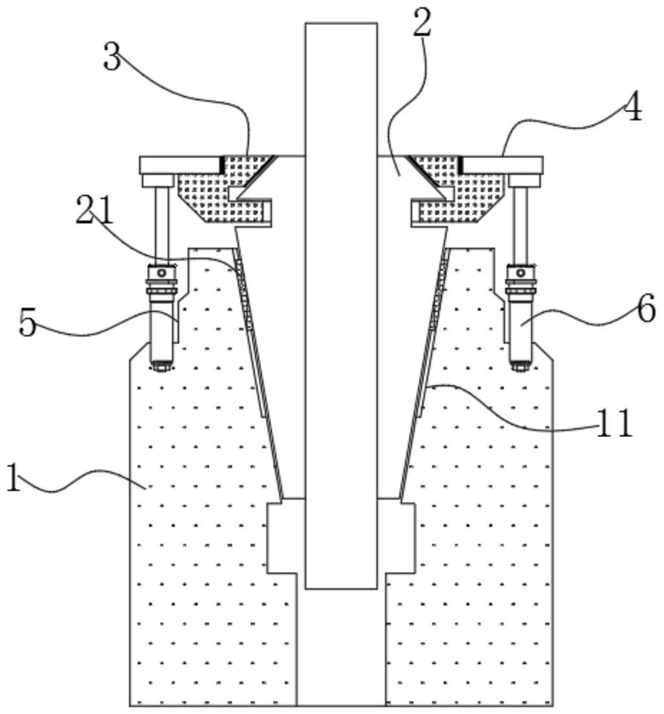
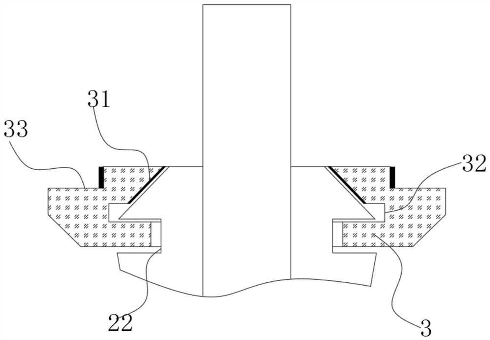
[0026] Specific implementation mode one: see Figure 1-4 This embodiment will be described. The clamping mechanism of the collet collet of the CNC lathe described in this embodiment includes a tool handle 1, a clamping sleeve 3 and a telescopic rod 6, wherein a through slot is opened in the middle of the tool handle 1 for passing a tool, and the There is also a tapered locking groove at the through groove at one end of the handle for locking the collet 2;

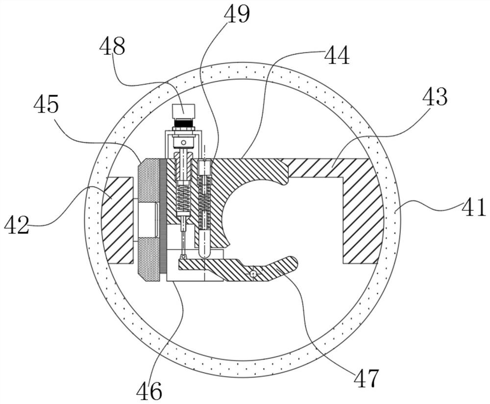
[0027] The outer sleeve of the collet 2 is provided with a clamping sleeve 3, and the clamping sleeve 3 is connected with a plurality of sets of telescopic rods 6 by a clamping assembly 4, and the other end of the telescopic rod 6 is fixedly embedded in the handle 1 ;

[0028] The clamping force exerted by the clamping assembly 4 on the clamping sleeve 3 can be absorbed by the clamping sleeve 3, preventing the clamping assembly 4 from applying a clamping force to the collet 2 through the clamping sleeve 3, so that The sp...


PUM


Abstract

The invention discloses a clamping mechanism for a collet chuck of a CNC lathe. The clamping mechanism is characterized in that a through groove is arranged in the middle of a tool bar and used for allowing a tool to pass through, and a conical locking groove is further arranged in the through groove in one end of the tool bar and used for locking the collet chuck; the collet chuck is sleeved with a clamping sleeve, the clamping sleeve is connected to a plurality of sets of telescopic rods through clamping components, and the other ends of the telescopic rods are fixedly embedded into the tool bar; the clamping force applied to the clamping sleeve by the clamping components can be absorbed by the clamping sleeve; and the collet chuck can be driven to move towards the tool bar through contraction of the telescopic rods, so that the tool located in the collet chuck is locked step by step, the collet chuck and the tool in the collet chuck are stressed more uniformly, the situation that the tool shakes in the machining process is reduced, and the problems that an existing clamping mechanism is generally of a nut structure, the collet chuck is locked on the tool bar through a nut, the clamping and fixing effect is common, and the uniform locking force on the tool cannot be guaranteed are solved.

Description

technical field [0001] The invention relates to a spring collet clamping mechanism of a numerically controlled lathe, belonging to the technical field of collet clamping mechanisms. Background technique [0002] CNC lathes have a wide range of processing performance, which can process complex workpieces such as straight cylinders, oblique cylinders, arcs, and various threads. The cylindrical fixture that confines the drill bit or milling cutter. When in use, place the tool in the collet, and lock the collet on the handle of the tool through the clamping mechanism. At present, the existing clamping mechanism Generally, it is a nut structure. The spring collet is locked on the tool handle through the nut. Its clamping and fixing effect is general, and it cannot ensure uniform locking force on the tool. Specifically, it cannot use the tool handle and the spring clip. The head provides a uniform and suitable locking force for the tool, so it is easy to cause the tool to vibrate...

Claims


Application Information

Patent Timeline
Patent Type & Authority Applications(China)
IPC IPC(8): B23B31/20
CPCB23B31/20
Inventor 刘光毅
Owner CHANGZHOU INST OF MECHATRONIC TECH
Why Eureka
Try Eureka