
A loading and unloading machine tool based on automatic manipulator

A technology of manipulators and machine tools, applied in the field of manipulators, can solve problems such as uneven clamping force of the clamping arm, downward movement of materials, troubles in use, etc., and achieve good clamping effect

Active Publication Date: 2022-05-24
JIANGSU NANGAO INTELLIGENT EQUIP INNOVATION CENT CO LTD
View PDF16 Cites 0 Cited by
  • Summary
  • Abstract
  • Description
  • Claims
  • Application Information

AI Technical Summary

Problems solved by technology

[0003] At present, when the circular flake material is transported in the market, the edge of the material is clamped and transported by using the clamping arm. During the process of transport, the material itself will be stacked layer by layer, and the gravity of the material itself will make the material In the process of transportation, there is a large friction with the inner wall of the clamping arm, and the length of the clamping arm is longer. The push of the electric push rod makes the clamping force of the clamping arm uneven, and the material will occur during the transportation process. The phenomenon of downward movement will cause the edge of the material and the inner wall of the clamping arm to be worn, which will cause troubles for the user in the later use

Method used

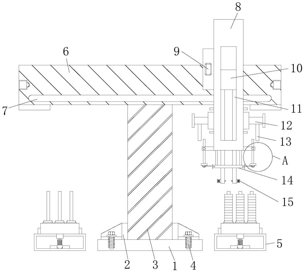

Image

  • A loading and unloading machine tool based on automatic manipulator
  • A loading and unloading machine tool based on automatic manipulator
  • A loading and unloading machine tool based on automatic manipulator

Examples


Embodiment Construction

[0028] The technical solutions in the embodiments of the present invention will be clearly and completely described below with reference to the accompanying drawings in the embodiments of the present invention. Obviously, the described embodiments are only a part of the embodiments of the present invention, rather than all the embodiments. Based on the embodiments of the present invention, all other embodiments obtained by those of ordinary skill in the art without creative efforts shall fall within the protection scope of the present invention.

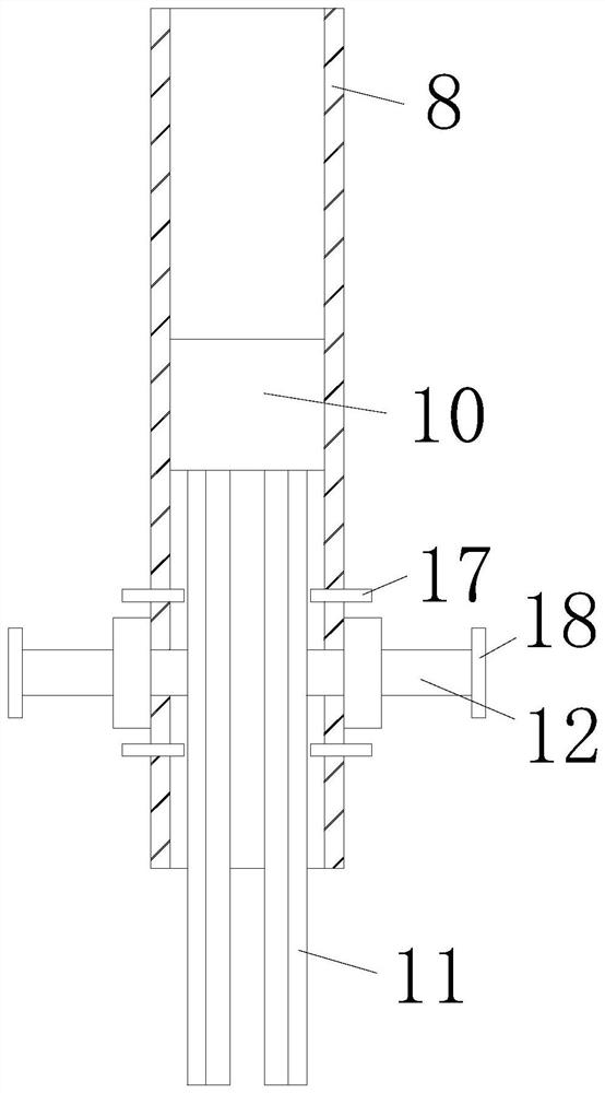
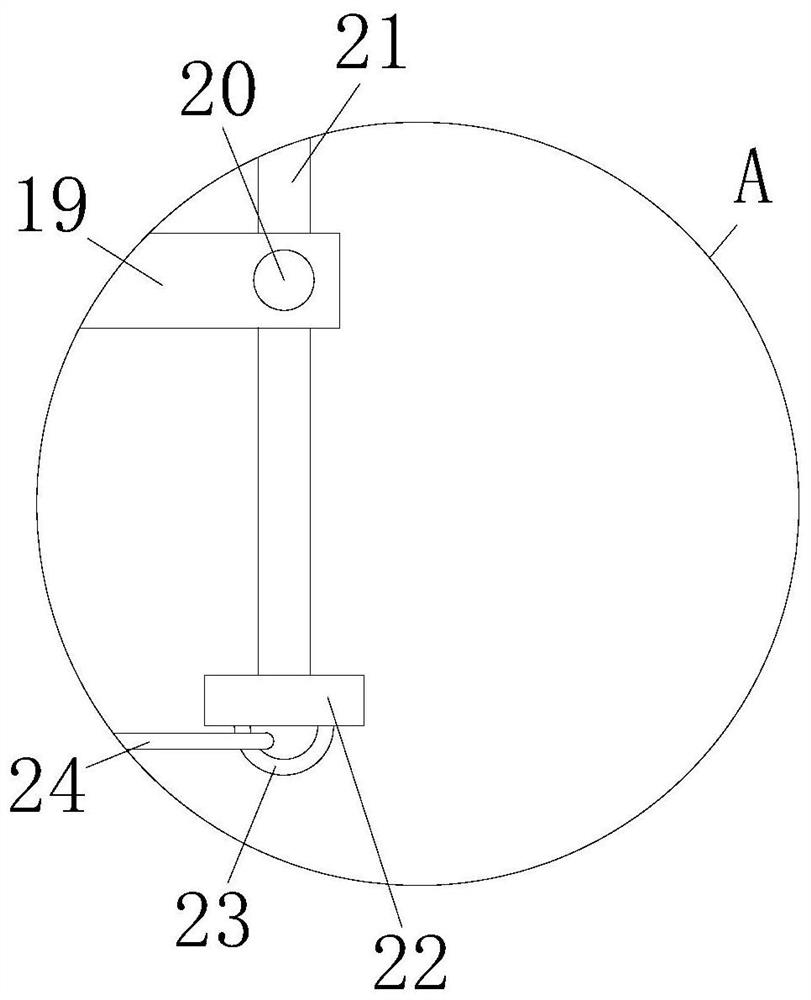
[0029] see Figure 1-6 , an automatic manipulator-based loading and unloading machine tool, comprising a base plate 1, a support column 3 is fixedly connected to the top of the base plate 1, a material loading mechanism 5 is arranged on one side of the support column 3, and a connector 2 is fixedly connected to the outer wall of the support column 3 , the top of the connector 2 is provided with a bolt 4, the top of the support column...


PUM


Abstract

The invention relates to the technical field of manipulators, and discloses a loading and unloading machine tool based on automatic manipulators, including a base plate, a support column is fixedly connected to the top of the base plate, and a loading mechanism is provided on one side of the support column. The outer wall is fixedly connected with a connecting piece, the top of the connecting piece is provided with a bolt, the top of the supporting column is fixedly connected with a crossbeam, the front of the crossbeam is provided with a slideway, and the crossbeam is movably connected with a column through the slideway, A drive is fixedly installed on one side of the column. The automatic manipulator-based loading and unloading machine tool achieves the purpose of good clamping effect, and solves the problem that the edge of the material and the inner wall of the clamping arm are worn due to the downward movement of the material during the handling of circular sheet materials. At the same time, the push plate provides clamping force for the bottom of the clamping arm, which balances the driving force received by the clamping arm and solves the problem of uneven clamping caused by the long length of the clamping arm.

Description

technical field [0001] The invention relates to the technical field of manipulators, in particular to a loading and unloading machine tool based on an automatic manipulator. Background technique [0002] The truss manipulator is a fully automatic industrial equipment based on the rectangular X, Y, Z three-coordinate system, which can adjust the position of the workpiece or realize the trajectory movement of the workpiece. Its control core is realized by industrial controllers (such as PLC, motion control and single-chip microcomputer, etc.). Through the analysis and processing of various input (various sensors and buttons, etc.) signals by the controller, after making a certain logical judgment, the execution command is issued to each output element (relay, motor driver and indicator light, etc.) to complete X, Y , the joint movement between the three axes of Z, in order to achieve a complete set of fully automatic operation process. [0003] At present, when handling circ...

Claims


Application Information

Patent Timeline
Patent Type & Authority Patents(China)
IPC IPC(8): B23Q7/04B23Q7/00
CPCB23Q7/04B23Q7/00B23Q7/043
Inventor 夏志杰张志胜
Owner JIANGSU NANGAO INTELLIGENT EQUIP INNOVATION CENT CO LTD
Learn More