Automatic cleaning machine for gravure rollers of printing machine

An automatic cleaning machine and gravure roller technology, which is applied to printing presses, general parts of printing machinery, printing and other directions, can solve the problems of occupying the effective printing time of the printing press, the long time for cleaning the plate rollers, and the waste of material resources. Achieve the effect of compact structure, lower production cost and lower labor cost

Pending Publication Date: 2021-05-25
ZHEJIANG MEIGE MACHINERY
View PDF0 Cites 1 Cited by
  • Summary
  • Abstract
  • Description
  • Claims
  • Application Information

AI Technical Summary

Problems solved by technology

Because the mesh pit of the version roller is very small, it takes a long time to clean the version roller, and the effective printing working time of the printing machine needs to be occupied when cleaning the version roller; in addition, the water and cleaning liquid for manual cleaning of the version roller are also used It is directly discharged at one time, resulting in a large waste of material resources and increasing production costs

Method used


Image

  • Automatic cleaning machine for gravure rollers of printing machine
  • Automatic cleaning machine for gravure rollers of printing machine
  • Automatic cleaning machine for gravure rollers of printing machine

Examples


Embodiment Construction

[0046] Further description will be given below in conjunction with the embodiments shown in the accompanying drawings.

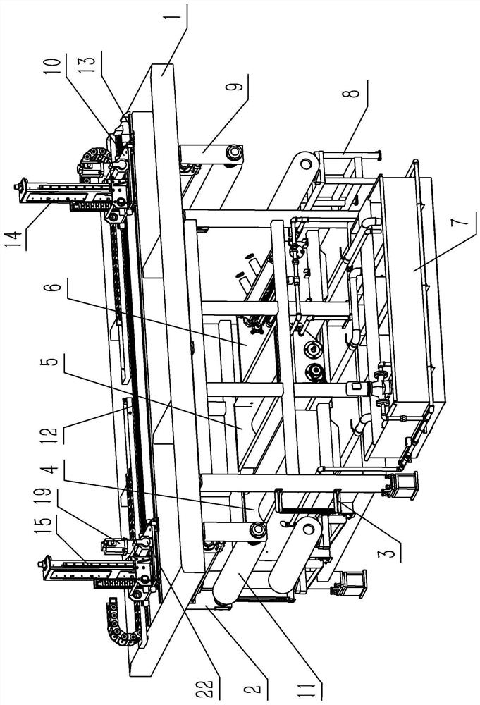
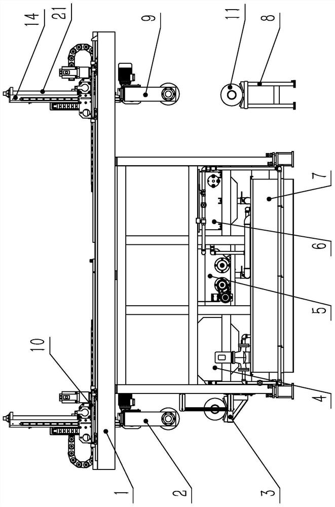
[0047] For convenience of description, the image 3 The left side of is left, the right side is right, image 3 The upper side of is up, and the lower side is down.

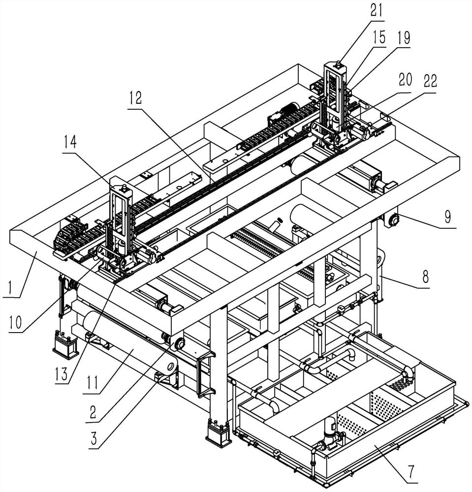
[0048] Such as Figure 1 to Figure 5The shown automatic gravure roller cleaning machine for printing machines includes a frame 1, two support frames 10, two autorotation mechanical arms (including the first autorotation robotic arm 2 and the second autorotation robotic arm 9), rough cleaning tank 4, ultrasonic Washing tank 5 , cleaning and drying device 6 , feeding transfer frame 3 , transfer table 8 and circulating water treatment equipment 7 . The rough washing tank, ultrasonic plate washing tank and cleaning and drying device are all arranged at the lower part of the frame and arranged in sequence from left to right. The feeding transfer frame is installed on the side of the rough cleani...


PUM


Abstract

The invention relates to the field of large gravure press corollary equipment. According to the technical scheme, an automatic cleaning machine for gravure rollers of a printing machine is characterized by comprising a rack, two supporting frames, two self-rotation mechanical arms, three cleaning assemblies and circulating water treatment equipment, wherein the two supporting frames are horizontally and slidably positioned on the upper portion of the rack in the left-right direction through first transmission assemblies correspondingly, the two self-rotation mechanical arms are vertically and slidably positioned on the two supporting frames through second transmission assemblies correspondingly, the three cleaning assemblies are arranged on the lower portion of the rack to clean and dry the gravure rollers, and the circulating water treatment equipment is used for providing cleaning water and collecting and treating sewage; the three cleaning assemblies are a rough cleaning tank, an ultrasonic plate cleaning tank and a cleaning and blow-drying device which are sequentially arranged from left to right; a feeding transfer frame used for containing the to-be-cleaned gravure rollers is installed on the side face of the rough cleaning tank; and a transfer table used for containing the clean gravure rollers is installed on the side face of the cleaning and blow-drying device. According to the automatic cleaning machine, the cleaning efficiency and the cleaning quality of the gravure rollers can be improved, manpower is greatly saved, and the production cost is reduced.

Description

technical field [0001] The invention relates to the field of supporting equipment for large gravure printing machines, in particular to an automatic cleaning machine for gravure rollers of a gravure printing machine after printing. Background technique [0002] At present, the plate rollers used in gravure printing machines need to be cleaned before they can be put into storage after a pattern is printed. The existing method of cleaning the plate roller is to turn on the printing machine again under the non-printing condition after the printing machine is printed, so that the plate roll runs slowly on the printing equipment, and then manually use clear water, plate brush and chemical solvent to align the plate manually The surface of the roller is brushed and cleaned with water. Because the mesh pit of the version roller is very small, it takes a long time to clean the version roller, and the effective printing working time of the printing machine needs to be occupied when ...

Claims


Application Information

Patent Timeline
IPC IPC(8): B41F35/02F26B21/00
CPCB41F35/02F26B21/004
Inventor 刘国方任耀庭屈瑶
Owner ZHEJIANG MEIGE MACHINERY
Why Eureka
Try Eureka