An anti-subsidence construction concrete pipe pile and its installation method

A technology for concrete pipe piles and anti-sinking, which is applied in construction, sheet pile walls, and foundation structure engineering, etc., and can solve problems affecting construction progress, construction accuracy and construction safety, and pipe piles to prevent subsidence The adjustable structure of the sinking stable limit structure ensures the anti-sinking effect and the effect of ensuring the service life

Active Publication Date: 2022-06-17
福建省二建建设集团有限公司
View PDF0 Cites 0 Cited by
  • Summary
  • Abstract
  • Description
  • Claims
  • Application Information

AI Technical Summary

Problems solved by technology

[0004] In order to solve the problems raised in the above-mentioned background technology, the purpose of the present invention is to provide an anti-sinking construction concrete pipe pile and its installation method, which has the advantages of an anti-sinking stable limit structure, adjustable structure and stable structure, and solves the problem of existing concrete piles. After the construction of soil pipe piles, there is a phenomenon that the pipe piles sink. The pipe piles sink by their own weight and there is no resistance structure on the surface to organize the sinking, which affects the construction accuracy and construction safety. At the same time, most of the limit structures during construction are The prefabricated ones cannot be adjusted relative to the on-site construction, which reduces the efficiency and accuracy of the construction, and due to the complex and changeable construction environment, the prefabricated completed structures cannot be adjusted, which will affect the construction progress.

Method used


Image

  • An anti-subsidence construction concrete pipe pile and its installation method
  • An anti-subsidence construction concrete pipe pile and its installation method
  • An anti-subsidence construction concrete pipe pile and its installation method

Examples


Embodiment Construction

[0035] The technical solutions in the embodiments of the present invention will be clearly and completely described below with reference to the accompanying drawings in the embodiments of the present invention. Obviously, the described embodiments are only a part of the embodiments of the present invention, rather than all the embodiments. Based on the embodiments of the present invention, all other embodiments obtained by those of ordinary skill in the art without creative efforts shall fall within the protection scope of the present invention.

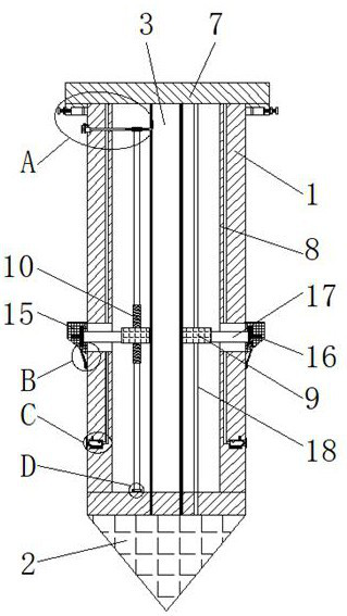
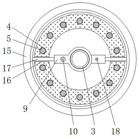
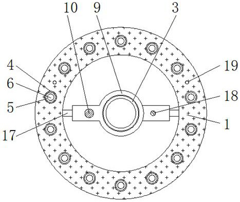
[0036] like Figure 1 to Figure 8 As shown in the figure, an anti-subsidence construction concrete pipe pile provided by the present invention includes a concrete pipe pile body 1, the bottom of the concrete pipe pile body 1 is fixedly connected with a pile tip 2, and the inner side of the concrete pipe pile body 1 is provided with an inner wall steel pipe 3 , the interior of the concrete pipe pile body 1 is provided with a mounting ...


PUM


Abstract

The invention discloses an anti-sinking construction concrete pipe pile and an installation method thereof, comprising a concrete pipe pile body, and a pile point is fixedly connected to the bottom of the concrete pipe pile body. In the present invention, the damping shock absorber is placed on the pile nail, and then the adjusting frame is placed on the surface of the inner wall steel pipe, and the installation is completed with the screw rod, and then the pile cap is placed on the top of the concrete pipe pile body, and the hammering operation can be performed to solve the problem. The existing concrete pipe piles have the phenomenon of pipe piles sinking after construction. The pipe piles sink due to their own weight and there is no resistance structure on the surface to make them sink, which affects the construction accuracy and construction safety. At the same time, the construction time limit Most of the bit structures are prefabricated, and the on-site construction cannot be adjusted accordingly, which reduces the efficiency and accuracy of the construction, and the construction progress is affected if the prefabricated structures cannot be adjusted due to the complex and changeable construction environment.

Description

technical field [0001] The invention relates to the technical field of concrete pipe piles, in particular to an anti-subsidence building concrete pipe pile and an installation method. Background technique [0002] With the development of reform and opening up and economic construction, prestressed concrete pipe piles have been widely used in railway systems, and gradually expanded to industrial and civil construction, municipal, metallurgy, ports, highways and other fields. Due to geological conditions, the Yangtze River Delta and The Pearl River Delta region is more suitable for the application of pipe piles. At present, pipe piles account for about 50% of the output value of the national cement products industry. (PC pipe pile) and prestressed concrete thin-walled pipe pile (PTC pipe pile) and high-strength prestressed concrete pipe pile (PHC pipe pile). It is a hollow cylindrical slender concrete prefabricated component made by the method, which is mainly composed of a c...

Claims


Application Information

Patent Timeline
Patent Type & Authority Patents(China)
IPC IPC(8): E02D5/30E02D5/22E02D7/00E02D13/00
CPCE02D5/30E02D5/22E02D7/00E02D13/00
Inventor 贺好
Owner 福建省二建建设集团有限公司
Why Eureka
Try Eureka