A modular building assembly structure

An assembly structure and modular technology, applied in building construction, construction, building maintenance, etc., can solve problems such as time-consuming, troublesome screwing of steel pipes and steel pipe sleeves, etc., and achieve the effect of prolonging the service life

Active Publication Date: 2022-04-19
SHENZHEN BUILDING DECORATION (GRP) CO LTD
View PDF5 Cites 0 Cited by
  • Summary
  • Abstract
  • Description
  • Claims
  • Application Information

AI Technical Summary

Problems solved by technology

[0002] During the construction of high-rise buildings, the workers first build the building brackets, that is, first build the external brackets of the high-rise buildings, and then proceed to the next step. In modular buildings, in the initial stage of building the building brackets, that is, in the It usually takes a long time to build the bottom ground support. The bottom end of the ground support is equipped with a steel pipe sleeve, and the steel pipe sleeve is threaded together with one end of the steel pipe. support, but the steel pipe and the steel pipe sleeve are more troublesome and time-consuming to screw up. If an assembly structure specially used for screwing the steel pipe and the steel pipe sleeve can be manufactured, the construction period will be greatly shortened. Therefore, the present invention proposes a Modular Building Assembly Structure

Method used


Image

  • A modular building assembly structure
  • A modular building assembly structure
  • A modular building assembly structure

Examples


Embodiment Construction

[0030] The following will clearly and completely describe the technical solutions in the embodiments of the present invention with reference to the accompanying drawings in the embodiments of the present invention. Obviously, the described embodiments are only some, not all, embodiments of the present invention.

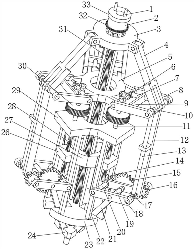
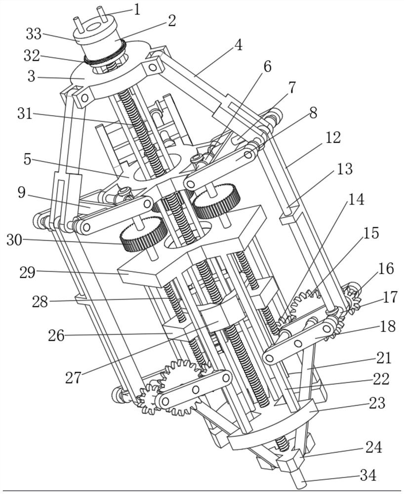
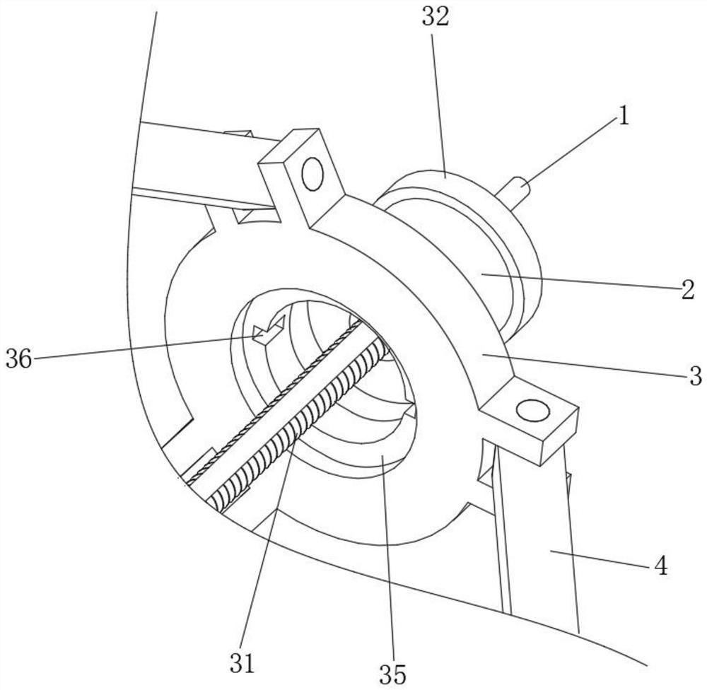
[0031] refer to Figure 1-5 , a modular building assembly structure, including a first push plate 3, the bottom surface of the first push plate 3 is provided with a circular groove 35, and the bottom surface of the circular groove 35 is provided with two limiting grooves 36 , the circular groove 35 is compatible with the steel pipe sleeve, and the limit groove 36 is compatible with the limit blocks on both sides of the steel pipe sleeve;

[0032] The sides of the first push pedal 3 are equidistantly hinged with three first connecting rods 4, the bottom side of the first push pedal 3 is provided with a first fixed plate 5, and the first push pedal 3 and the first fixe...


PUM


Abstract

The present invention relates to the technical field of building assembly structures, especially a modular building assembly structure. The following proposal is proposed, which includes a first push plate, a circular groove is formed on the bottom surface of the first push plate, and a circular groove is formed on the bottom surface of the circular groove. There are two limit slots, the side of the first push plate is equidistantly hinged with three first connecting rods, the bottom side of the first push plate is provided with a first fixed plate, and the end faces of the first push plate and the first fixed plate They are all circular, and the side of the first fixed plate is equidistantly provided with three first rotating columns, and the first rotating columns are all rotatably connected with the first fixed plate, and the two ends of the three first rotating columns are rotatably connected with the second As for the connecting rod, the third rotating column is rotatably connected between the two second connecting rods on the first rotating column, and one end of the first connecting rod is rotatably connected with the corresponding third rotating column. The invention achieves the purpose of screwing the steel pipe and the steel pipe sleeve together, repairing the depression on the outer wall of the steel pipe, and ensuring the firmness of the steel pipe.

Description

technical field [0001] The invention relates to a building assembly structure, in particular to a modular building assembly structure. Background technique [0002] During the construction of high-rise buildings, the workers first build the building brackets, that is, first build the external brackets of the high-rise buildings, and then proceed to the next step. In modular buildings, in the initial stage of building the building brackets, that is, in the It usually takes a long time to build the bottom ground support. The bottom end of the ground support is equipped with a steel pipe sleeve, and the steel pipe sleeve is threaded together with one end of the steel pipe. support, but the steel pipe and the steel pipe sleeve are more troublesome and time-consuming to screw up. If an assembly structure specially used for screwing the steel pipe and the steel pipe sleeve can be manufactured, the construction period will be greatly shortened. Therefore, the present invention prop...

Claims


Application Information

Patent Timeline
Patent Type & Authority Patents(China)
IPC IPC(8): E04G21/16E04G23/02B05C1/06B23P19/04B24B27/033B24B5/40B24B5/35B24B41/04B24B47/20
CPCE04G21/16E04G23/02B05C1/06B23P19/04B24B27/033B24B5/40B24B5/35B24B41/04B24B47/20
Inventor 吴富贵王俊李申玉
Owner SHENZHEN BUILDING DECORATION (GRP) CO LTD
Why Eureka
Try Eureka