
Clamp holder for nuclear magnetic resonance system

A technology of nuclear magnetic resonance and clamper, which is applied in the direction of analysis by nuclear magnetic resonance, workpiece clamping device, material analysis through resonance, etc., can solve the problem that it is difficult to meet the performance requirements of high pressure and high temperature resistance, and achieve the reduction of heat conduction phenomenon, Easy to connect and fix, increase the effect of strength

Pending Publication Date: 2021-05-25
SUZHOU NIUMAG ELECTRONICS TECH
View PDF0 Cites 0 Cited by
  • Summary
  • Abstract
  • Description
  • Claims
  • Application Information

AI Technical Summary

Problems solved by technology

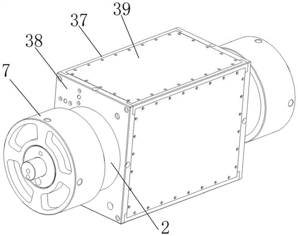
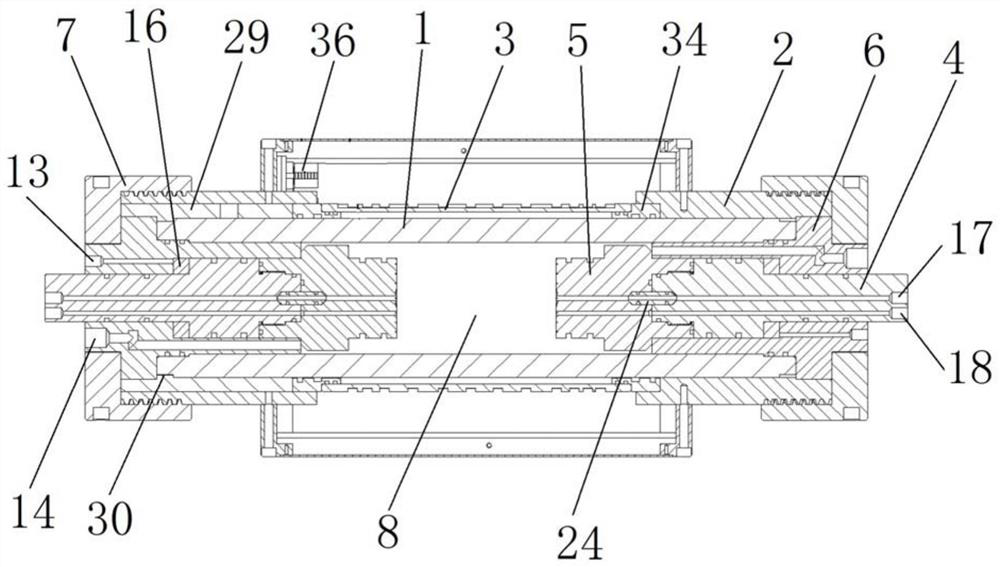
[0004] Therefore, the technical problem to be solved by the present invention is to overcome the defects in the prior art that the nuclear magnetic resonance radio frequency coil is placed inside the holder, which is difficult to meet the performance requirements of high pressure and high temperature resistance, thereby providing a holder for nuclear magnetic resonance systems

Method used


Image

  • Clamp holder for nuclear magnetic resonance system
  • Clamp holder for nuclear magnetic resonance system
  • Clamp holder for nuclear magnetic resonance system

Examples


Embodiment Construction

[0050] The technical solutions of the present invention will be clearly and completely described below in conjunction with the accompanying drawings. Apparently, the described embodiments are some of the embodiments of the present invention, but not all of them. Based on the embodiments of the present invention, all other embodiments obtained by persons of ordinary skill in the art without making creative efforts belong to the protection scope of the present invention.

[0051] In the description of the present invention, it should be noted that the terms "center", "upper", "lower", "left", "right", "vertical", "horizontal", "inner", "outer" etc. The indicated orientation or positional relationship is based on the orientation or positional relationship shown in the drawings, and is only for the convenience of describing the present invention and simplifying the description, rather than indicating or implying that the referred device or element must have a specific orientation, ...


PUM


Abstract

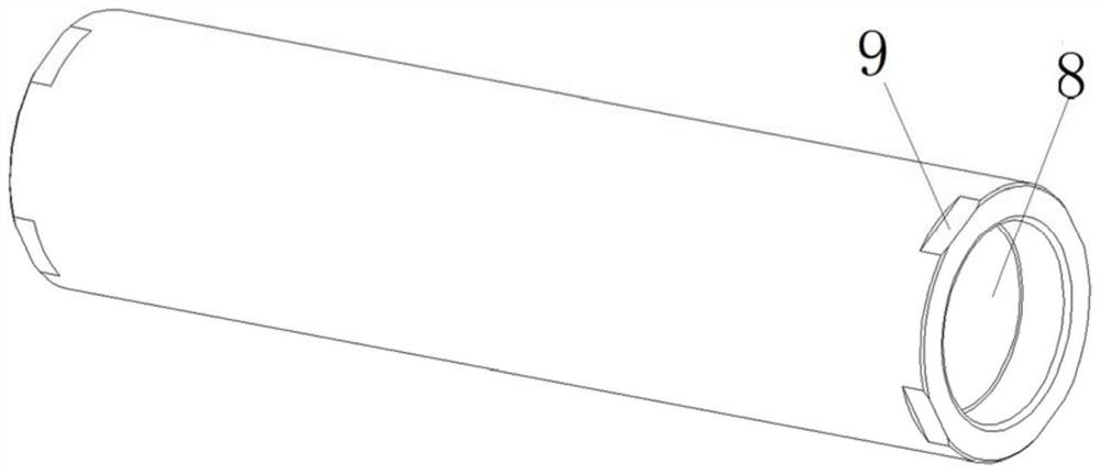
The invention provides a clamp holder for a nuclear magnetic resonance system, and belongs to the technical field of nuclear magnetic resonance detection. The clamp holdercomprises a clamping main body made of a non-metal material and provided with an accommodating cavity for placing a sample; an annular framework which is arranged on the outer wall of the clamping main body in a sleeving manner, wherein a gap is formed between the annular framework and the outer wall of the clamping main body; and a radio frequency coil which is arranged around the outer wall of the annular framework. The clamping main body is made of a non-metal material, so that interference of paramagnetic substances on nuclear magnetic resonance signals is avoided; the annular framework is arranged on the outer wall of the clamping main body in a sleeving mode, the radio frequency coil surrounds the outer wall of the annular framework, and the radio frequency coil is prevented from bearing pressure in the clamping main body. A gap is formed between the annular framework and the outer wall of the clamping main body, so that heat transfer of the clamping main body to the radio frequency coil is reduced; According to the structure, the radio frequency coil does not need to bear pressure and high heat, so that the radio frequency coil made of a common material can meet the use requirement, and the design cost is low.

Description

technical field [0001] The invention relates to the technical field of nuclear magnetic resonance detection, in particular to a holder for a nuclear magnetic resonance system. Background technique [0002] In oil and gas exploration and development and deep rock mass engineering, there is a complex relationship of interaction and mutual restriction among the stress field, temperature field, seepage field and rock mass deformation field of the rock mass in the relevant formation. In the process of rock mass excavation and oil and gas exploitation, in order to avoid catastrophe induced by rock mass due to stress concentration and unloading and the impact of high temperature, high pressure, and high seepage on mining efficiency, it is necessary to take out rock samples from relevant strata to simulate the environment in which the rock is located To measure the porosity, permeability, saturation and other parameters of rock samples. [0003] The NMR holder mostly adopts an all-...

Claims


Application Information

Patent Timeline
Patent Type & Authority Applications(China)
IPC IPC(8): G01N24/08B25B11/00
CPCB25B11/00G01N24/081
Inventor 杨培强陆治勇袁国平许文强李文福张英力蔡清石志东
Owner SUZHOU NIUMAG ELECTRONICS TECH
Learn More