An anti-current backflow circuit for buck converter
A converter and circuit technology, applied in the electrical field, can solve the problems of narrow operating temperature range, current inversion, lack of anti-irradiation characteristics, etc., to achieve the effect of improving reliability and stability and preventing current inversion
- Summary
- Abstract
- Description
- Claims
- Application Information
AI Technical Summary
Problems solved by technology
Method used
Image

Examples
Embodiment Construction
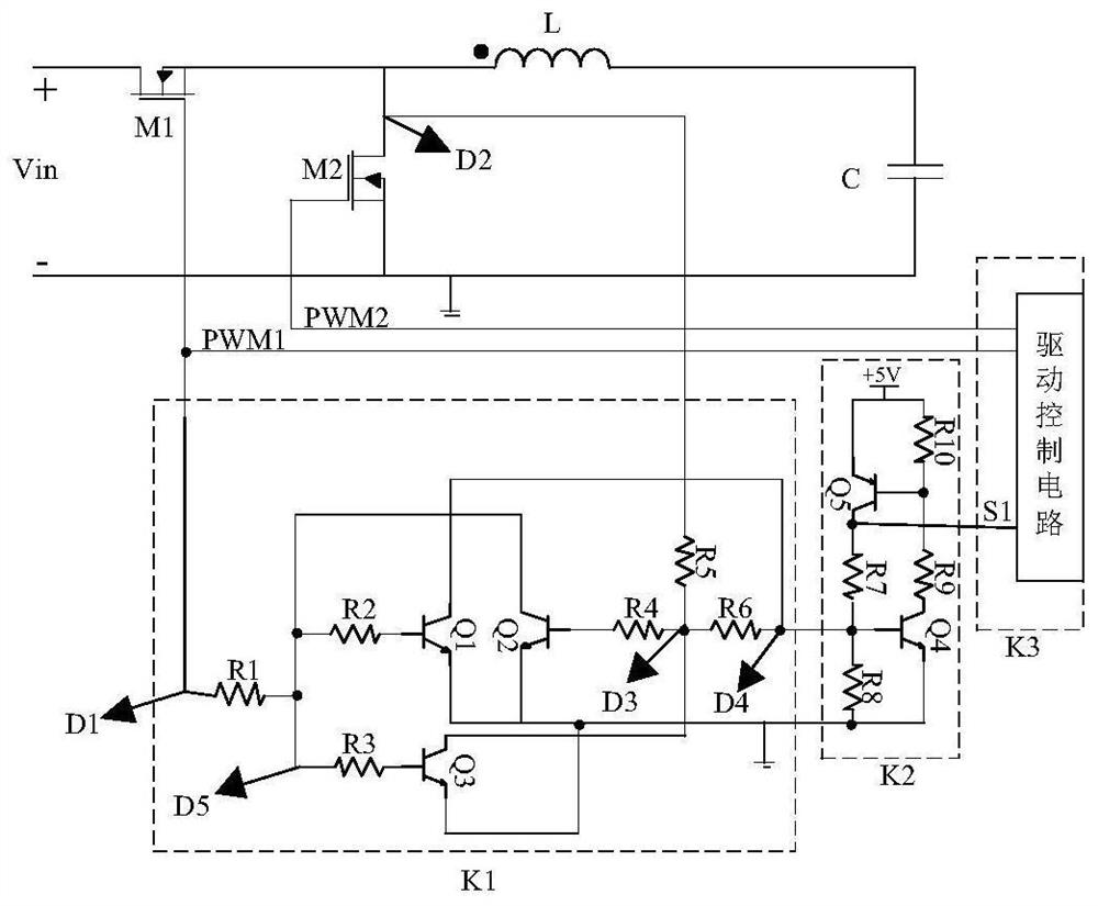
[0033] A current backflow prevention circuit for a BUCK converter of the present invention will be described in further detail below in conjunction with the accompanying drawings.
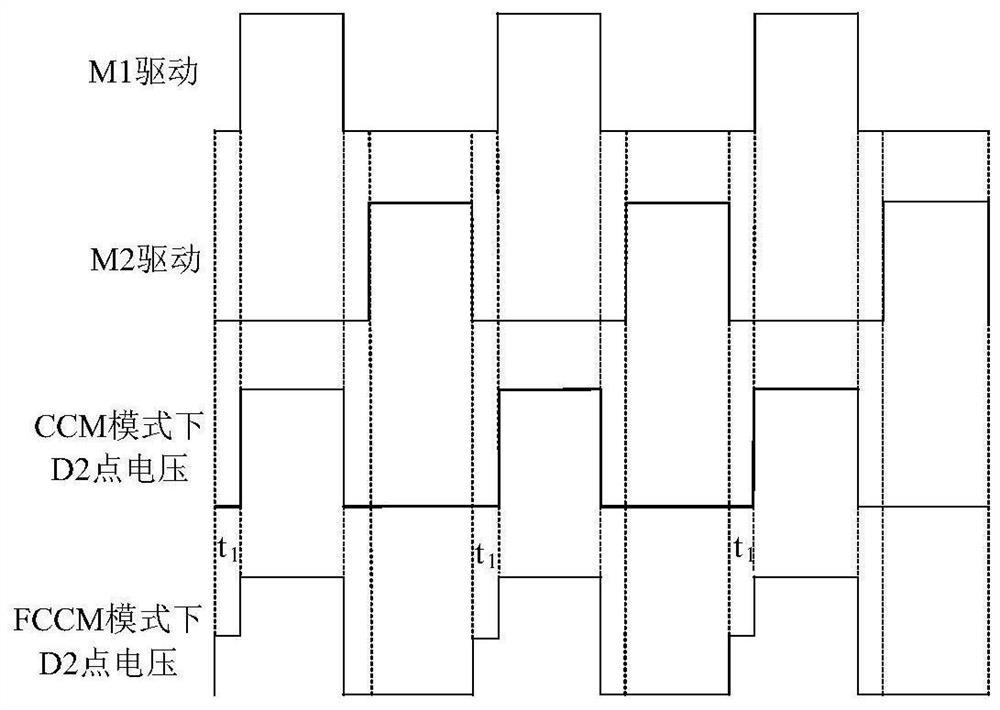
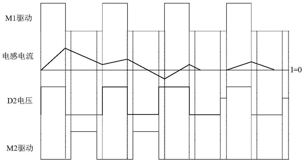
[0034] A kind of anti-current backfeed circuit based on the synchronous Buck circuit proposed by the present invention, the circuit is as figure 1As shown, it consists of three parts, the first part is composed of Q1, Q2, Q3, R1, R2, R3, R4 and R5. When the Buck converter is in the continuous conduction mode, if M1 changes from off to on, point D1 will become high level before point D2, so during the conduction period of M1, transistors Q1 and Q3 will switch D3 and D4 The voltage at the point is always clamped low. When M1 is turned off, the inductor current continues to flow through the body diode of M2 during the dead time. When M2 is turned on, the inductor current continues to flow through M2, so the voltage at point D2 is always low during the period when M1 is turned off. . During the whol...
PUM
 Abstract
Description
Claims
Application Information
 - R&D Engineer
- R&D Manager
- IP Professional
- Industry Leading Data Capabilities
- Powerful AI technology
- Patent DNA Extraction
Browse by: Latest US Patents, China's latest patents, Technical Efficacy Thesaurus, Application Domain, Technology Topic.
© 2024 PatSnap. All rights reserved.Legal|Privacy policy|Modern Slavery Act Transparency Statement|Sitemap