
Absorption tower slurry spray cooling white removal device

A technology of spray cooling and absorption tower, applied in lighting and heating equipment, separation of dispersed particles, chemical instruments and methods, etc., can solve the problems of reducing flue gas treatment efficiency, low flue gas treatment efficiency, affecting the speed of smoke exhaust, etc. , to achieve the effect of improving flue gas treatment efficiency, heat exchange effect and dewhitening effect, and thorough flushing

Inactive Publication Date: 2021-05-28
HANGZHOU BEIGAOFENG ELECTRIC POWER ENG DESIGN
View PDF8 Cites 0 Cited by
  • Summary
  • Abstract
  • Description
  • Claims
  • Application Information

AI Technical Summary

Problems solved by technology

Because the medium on both sides of the heat exchange tube of the conventional condensing module is water-flue gas, the heat transfer coefficient is small, the whitening effect is average, and the heat exchange area is made very large. It is often necessary to expand the diameter in the absorption tower to arrange it, resulting in occupation Large area, high operation and maintenance costs; and the thickness of the heat exchange module in the direction of flue gas flow is relatively large, and the resistance of flue gas is also large, which affects the speed of smoke exhaust and reduces the treatment efficiency of flue gas
[0004] Therefore, the existing dewhitening devices have the problems of general dewhitening effect, high cost, and low flue gas treatment efficiency.

Method used


Image

  • Absorption tower slurry spray cooling white removal device
  • Absorption tower slurry spray cooling white removal device
  • Absorption tower slurry spray cooling white removal device

Examples


Embodiment Construction

[0030] The present invention will be further described below in conjunction with the examples, but not as a basis for limiting the present invention.

[0031] Example.

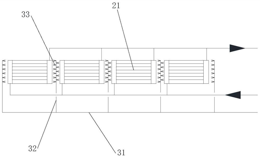
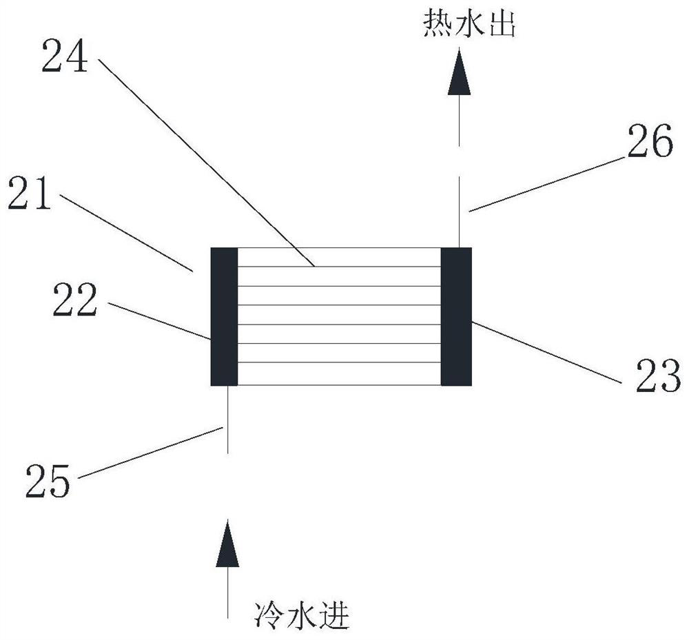
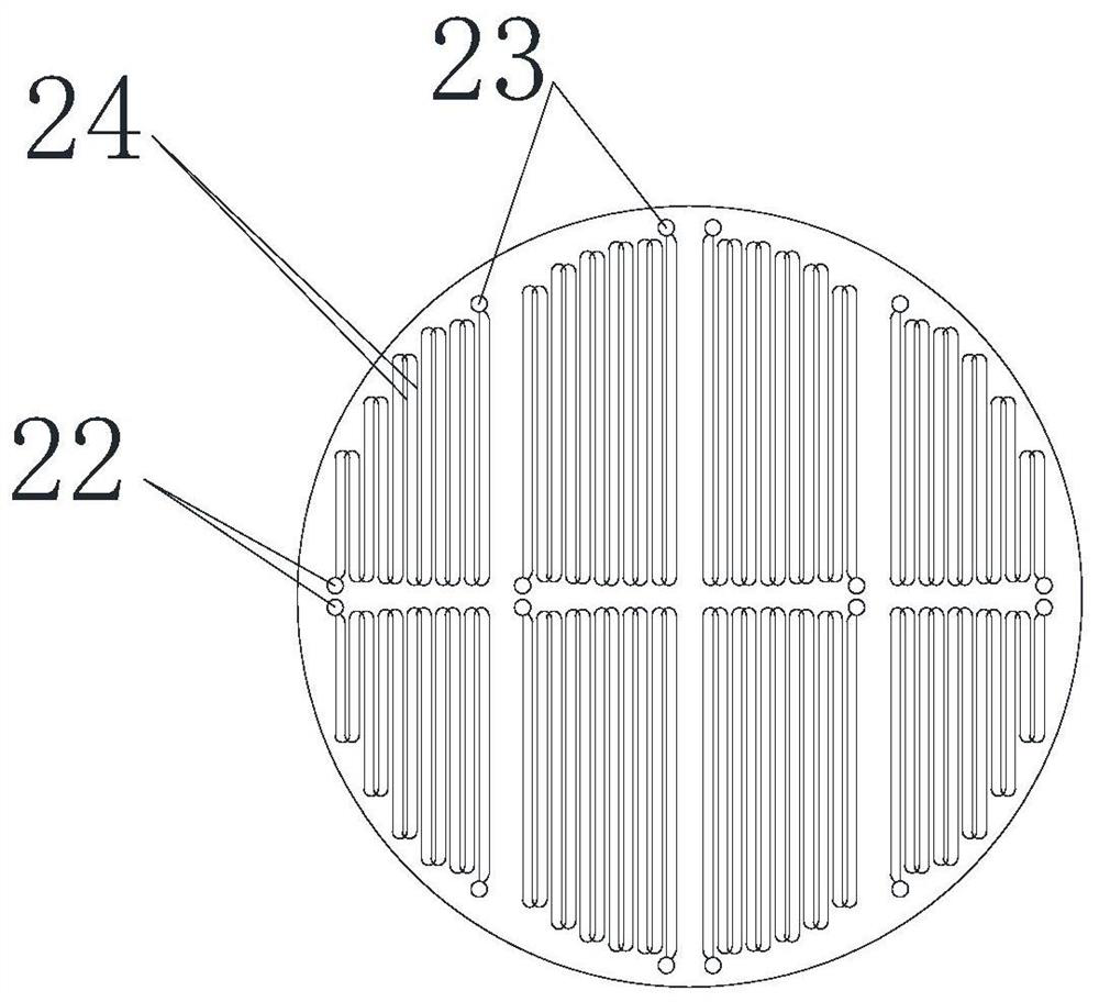
[0032] Such as Figure 1-6 As shown, the absorption tower slurry spray cooling dewhitening device includes a slurry cooling plate 2 composed of several condensation modules 21 installed below the spray layer 4 and a flushing device 3, and the condensation module 21 includes an inlet header 22 and an outlet The header 23, the inlet header 22 and the outlet header 23 are provided with several staggered heat exchange coils 24; the flushing device 3 includes a flushing main pipe 31, and several deep slurry cooling plates are arranged on the flushing main pipe 31 2 and located on both sides of the condensation module 21, the flushing branch pipe 32 is provided with a number of flushing nozzles 33 facing the condensation module 21. The flushing branch pipe 32 goes deep into the slurry cooling plate 2 for flushing, ...


PUM

PropertyMeasurementUnit
diameteraaaaaaaaaa
porosityaaaaaaaaaa

Abstract

The invention discloses an absorption tower slurry spray cooling white removal device, which comprises a slurry cooling disc (2) and a flushing device (3), the slurry cooling disc (2) is arranged below a spray layer (4) and consists of a plurality of condensation modules (21), each condensation module (21) comprises an inlet header (22) and an outlet header (23), and a plurality of heat exchange coils (24) distributed in a staggered manner are arranged between the inlet header (22) and the outlet header (23); and the flushing device (3) comprises a flushing main pipe (31), the flushing main pipe (31) is provided with a plurality of flushing branch pipes (32) which extend into the slurry cooling disc (2) and are located on the two sides of the condensation module (21), and the flushing branch pipes (32) are provided with a plurality of flushing nozzles (33) facing the condensation module (21). The device has the characteristics of good white smoke removal effect, low operation and maintenance cost and high flue gas treatment efficiency.

Description

technical field [0001] The invention relates to the technical field of wet desulfurization net flue gas treatment, in particular to a dewhitening device for absorbing tower slurry spray cooling. Background technique [0002] For the flue gas treatment of thermal power plants in my country, wet desulfurization devices are mainly used. However, the outlet of wet desulfurization is saturated or nearly saturated wet flue gas. The flue gas temperature is about 50°C. After the wet flue gas is discharged into the atmosphere through the chimney, it will condense in contact with low-temperature air, and a large number of condensed water droplets will produce light Refraction and scattering, resulting in a white or light gray smoke plume, causing visual pollution and smog. At present, the flue gas dewhitening device mainly uses the "condensation module", which is about cooling and drying the saturated wet flue gas from the spray layer of the absorption tower, forcing out the saturate...

Claims


Application Information

Patent Timeline
Patent Type & Authority Applications(China)
IPC IPC(8): B01D53/80B01D53/50B01D53/48F23J15/04
CPCB01D53/80B01D53/50B01D53/502B01D53/48F23J15/04B01D2251/404
Inventor 林崇军胡宏兴谭运雄路锦程左兵孙玺玺汪月鹏金志勇任永珍林华峰
Owner HANGZHOU BEIGAOFENG ELECTRIC POWER ENG DESIGN
Learn More