Furnace slag treatment intelligent factory based on Industry 4.0

A slag and industrial technology, applied in the field of slag processing intelligent chemical plant, can solve the problems of increasing processing time, device damage, reducing processing efficiency, etc., and achieve the effect of increasing work efficiency and realizing processing work

Inactive Publication Date: 2021-05-28
广东忠能科技集团有限公司
View PDF0 Cites 0 Cited by
  • Summary
  • Abstract
  • Description
  • Claims
  • Application Information

AI Technical Summary

Problems solved by technology

[0003] However, in the prior art, the existing slag processing equipment needs to feed the slag into the device from the feed port during use. Due to the different sizes of the slag, the existing slag processing device cannot filter the larger slag processing, which will cause damage to the device for larger slag, and also increase the processing time, thereby reducing the processing efficiency

Method used


Image

  • Furnace slag treatment intelligent factory based on Industry 4.0
  • Furnace slag treatment intelligent factory based on Industry 4.0
  • Furnace slag treatment intelligent factory based on Industry 4.0

Examples


Embodiment 1

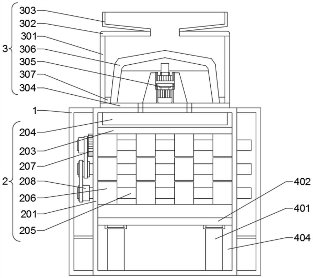
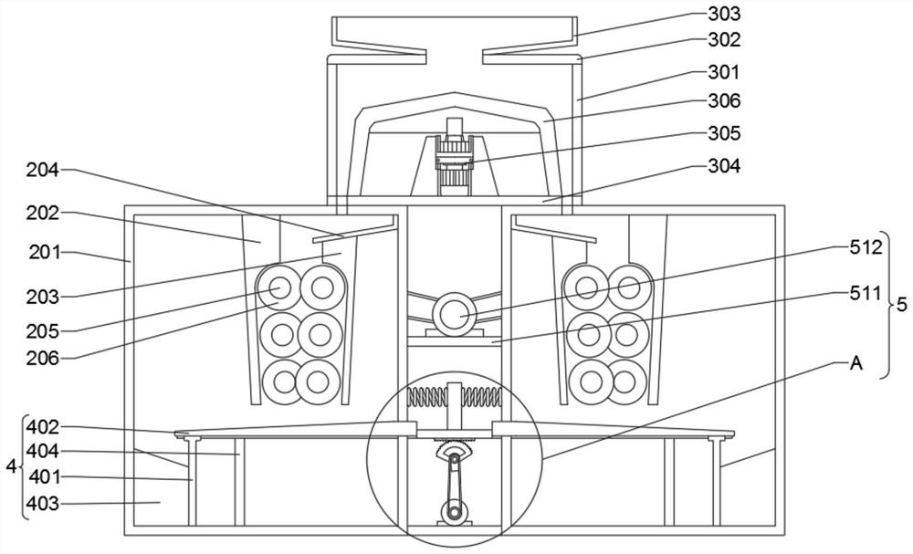
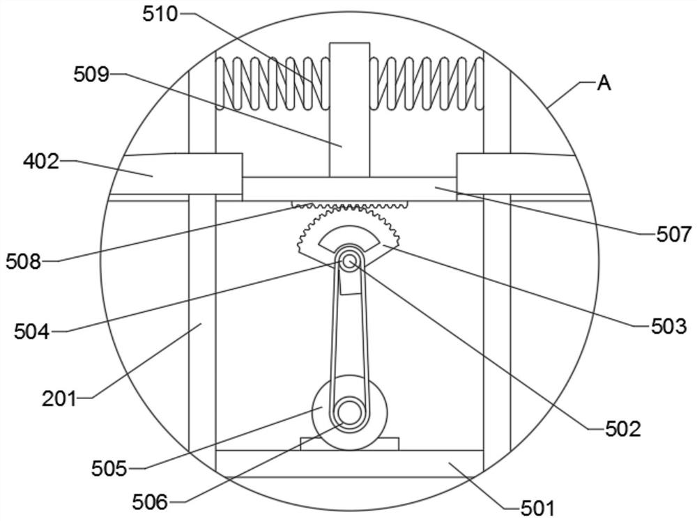
[0030] Example 1, such as Figure 1-4 As shown, the present invention provides an intelligent chemical plant for slag processing based on Industry 4.0, including a protective shell 1, two protective shells 1 are arranged in total, two processing mechanisms 2 are fixed between the front and rear surfaces of the two protective shells 1, and the two A crushing mechanism 3 is fixed between the tops of the two processing mechanisms 2, a filter mechanism 4 is fixed on the inner bottom surfaces of the two processing mechanisms 2, and a power mechanism 5 is arranged between the outer surfaces of one side of the two processing mechanisms 2;

[0031] The crushing mechanism 3 includes a first housing 301, the top of the first housing 301 is fixed with a cover plate 302, the top of the cover plate 302 is fixed with a feeding cylinder 303, the top center of the cover plate 302 is provided with a communication hole, and the communication hole The top of the first housing 301 is fixed with a...

Embodiment 2

[0033] Example 2, such as Figure 1-4 As shown, the processing mechanism 2 includes a second housing 201, the top of the second housing 201 is provided with a material inlet, and the top of the material inlet extends to the outside of the bottom plate 304, between the front and rear inner surface walls of the second housing 201 The first baffle plate 202 is welded, the second baffle plate 203 is welded on the side away from the first baffle plate 202 between the front and rear inner surface walls of the second housing 201, and the top of the second baffle plate 203 is welded with a fixing plate 204, Six first metal rods 205 are arranged between the front and rear inner surface walls of the second housing 201 near the first baffle plate 202 , and both ends of the six first metal rods 205 penetrate to the outside of the second housing 201 , the six first metal rods 205 are divided into two groups, and the outer surfaces of one group of three first metal rods 205 are equipped wit...


PUM


Abstract

The invention provides a furnace slag treatment intelligent factory based on Industry 4.0, and relates to the technical field of furnace slag treatment. The intelligent factory comprises two protective shells, wherein two treatment mechanisms are fixed between the front and rear surfaces of the two protective shells correspondingly, a crushing mechanism is fixed between the tops of the two treatment mechanisms, and filtering mechanisms are fixed on the inner bottom surfaces of the two treatment mechanisms correspondingly. According to the intelligent factory, through starting of a first motor, a rotating shaft can rotate, a crushing wheel can rotate while the rotating shaft rotates, and due to the fact that a plurality of crushing grooves are formed in the outer surface of the crushing wheel, in use, the working efficiency of the crushing wheel is improved, when the crushing wheel rotates, a scraper fixed on the outer surface of the crushing wheel is enabled to rotate, meanwhile, through the cooperation of a feeding opening in the bottom of a bottom plate, crushed furnace slag can be effectively moved into a device in use, and subsequent treatment of the furnace slag is facilitated.

Description

technical field [0001] The invention relates to the technical field of slag treatment, in particular to an intelligent chemical plant for slag treatment based on Industry 4.0. Background technique [0002] The slag is in a molten state when it is discharged, and it must be processed in a certain process to meet the requirements of the other party and the subsequent use. The slag can be processed in different ways to obtain finished products in different states. The finished slag can be used as cement mixing materials, paving, Production of glass-ceramics, etc., and in the process of processing, slag processing equipment is used. [0003] However, in the prior art, the existing slag processing equipment needs to feed the slag into the device from the feed port during use. Due to the different sizes of the slag, the existing slag processing device cannot filter the larger slag Processing, which will cause damage to the device for larger slag, and also increase the processing ...

Claims


Application Information

Patent Timeline
Patent Type & Authority Applications(China)
IPC IPC(8): B02C4/08B02C4/40B02C4/42
CPCB02C4/08B02C4/40B02C4/42
Inventor 李运忠顾桂荣
Owner 广东忠能科技集团有限公司
Why Eureka
Try Eureka