
Waste recycling device for energy-saving building construction

A technology for waste recycling and building construction, which is applied in the direction of separating solids from solids with airflow, solid separation, and screening, etc. It can solve the problems of poor screening effect and insufficient fine screening effect of building materials.

Inactive Publication Date: 2021-05-28
王亚超
View PDF10 Cites 0 Cited by
  • Summary
  • Abstract
  • Description
  • Claims
  • Application Information

AI Technical Summary

Problems solved by technology

[0004] In view of the above situation, in order to overcome the defects of the prior art, the present invention provides an energy-saving building construction waste recovery and reuse device, which effectively solves the problem of the need for the thickness of the construction waste when the construction waste on the market is reused. Screening and crushing of larger building materials. Due to the poor screening effect of existing materials, only smaller materials are screened, which affects the problem that the screening effect of building materials is not fine enough.

Method used


Image

  • Waste recycling device for energy-saving building construction
  • Waste recycling device for energy-saving building construction
  • Waste recycling device for energy-saving building construction

Examples


Embodiment 1

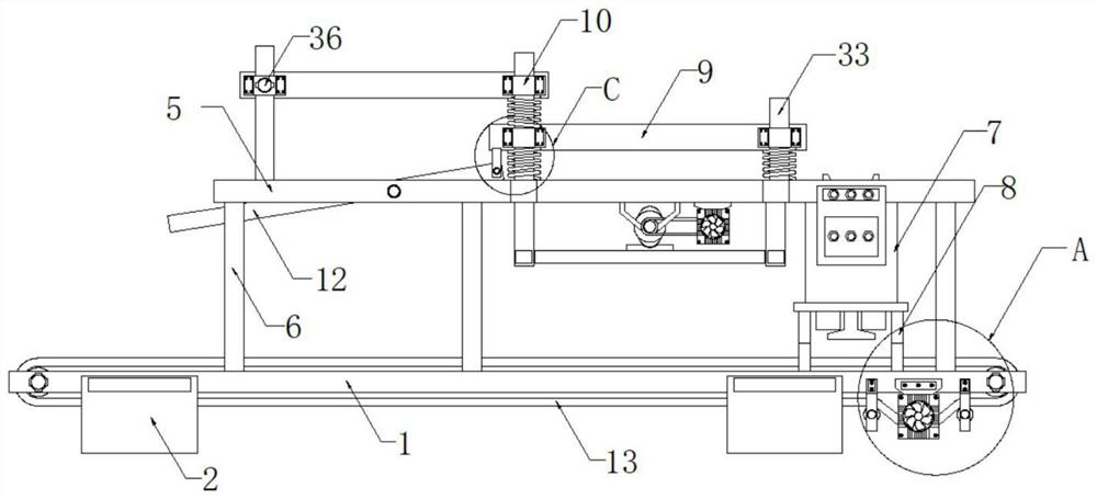
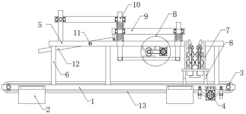
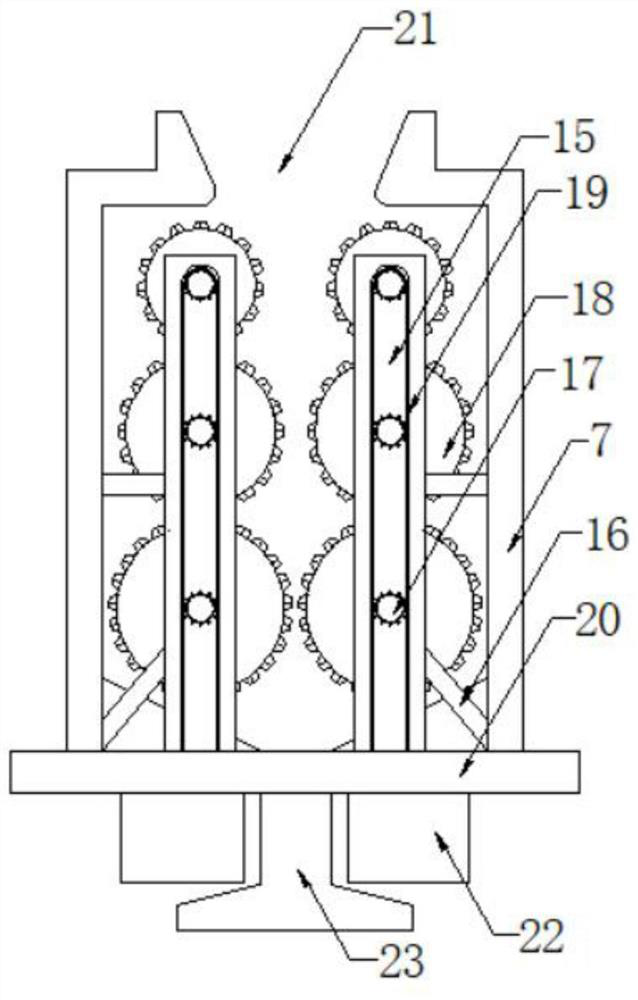
[0028] Embodiment one, by Figure 1-7Given, the present invention comprises support base plate 1, and the top of support base plate 1 is provided with sieve support 5, and the inner rotation socket of support base plate 1 is provided with two drive drums 3, and two drive drums 3 are centered on the axle center of support base plate 1 The center is symmetrically distributed, the outer rotation of the two drive rollers 3 is sleeved with a transmission belt 13, the inner wall of the transmission belt 13 is in contact with the outer wall of the supporting base 1, and the bottom of the supporting base 1 is fixedly installed with the first motor 4, the first motor 4 The output end of the output end is in contact with the inner wall of the transmission belt 13 through the rotating shaft round rod, and four rotating brackets 24 are fixedly installed on the bottom of the support base plate 1, and every two corresponding rotating brackets 24 form a group, and the inside of each rotating ...

Embodiment 2

[0029] Embodiment 2, on the basis of Embodiment 1, the insides of the two sleeves 10 are movably connected with connecting rods 36, and one ends of the two connecting rods 36 are movably connected to the inside of the screening plate 9 , so that one end of the screening plate 9 can be fixed on one side of one of the supporting frames 6 .

Embodiment 3

[0030] Embodiment three, on the basis of embodiment one, the inside of sieve plate 9 is provided with through-hole groove 37, and the inner wall of through-hole groove 37 is fixedly installed with several sorting plates 14, and several sorting plates 14 are evenly distributed Inside the through hole groove 37 .


PUM


Abstract

The invention relates to the technical field of construction waste treatment, discloses a waste recycling device for energy-saving building construction. The waste recycling device solves the problem that when building waste in the current market is recycled, the building waste needs to be screened according to the thickness degree, large-size building materials need to be crushed, due to the fact that existing material screening effect is poor, only small materials are screened, accordingly, the screening effect of the building materials is affected and not fine enough. The waste recycling device comprises a supporting bottom plate, wherein a screening support is arranged at the top of the supporting bottom plate, two transmission rollers are rotationally connected into the supporting bottom plate in a sleeved mode, and the two transmission rollers are symmetrically distributed with the axis of the supporting bottom plate as the center. According to the waste recycling device for energy-saving building construction, the building waste on a screening plate can be vibrated, screened and conveyed, the building waste can be crushed step by step, a subdivision screening plate is driven to vibrate, and therefore the building waste falling from the screening plate can be finely screened.

Description

technical field [0001] The invention belongs to the technical field of construction waste treatment, in particular to an energy-saving construction waste recovery and reuse device. Background technique [0002] Construction waste refers to the dregs, spoils, waste materials, silt and other wastes generated during the construction, laying or demolition, and repair of various buildings, structures, and pipe networks by construction units or individuals. Garbage refers to the general designation of muck, waste concrete, waste masonry and other waste generated by people in the production activities of the construction industry such as demolition, construction, decoration, and repair. According to the classification of generation sources, construction waste can be divided into engineering dregs , decoration waste, demolition waste, engineering mud, etc., classified according to the composition, construction waste can be divided into muck, concrete blocks, crushed stones, brick an...

Claims


Application Information

Patent Timeline
IPC IPC(8): B02C4/08B02C4/28B02C23/14B02C23/02B07B9/00B07B1/28B07B1/42B07B1/46
CPCB02C4/08B02C4/28B02C4/286B02C23/14B07B9/00B07B1/28B07B1/42B07B1/46B02C2201/06
Inventor 王亚超李红玉鬲鹏飞
Owner 王亚超
Learn More