Fiber regeneration machine

A regenerator and fiber technology, applied in grain processing and other directions, can solve the problems of reducing material crushing effect, taking longer time, reducing cutting frequency, etc., and achieving the effect of shortening crushing time, reducing energy consumption, and increasing cutting frequency

Pending Publication Date: 2021-05-28
SHANDONG JIEFENG MACHINERY MFG
View PDF0 Cites 1 Cited by
  • Summary
  • Abstract
  • Description
  • Claims
  • Application Information

AI Technical Summary

Problems solved by technology

[0004] from figure 1 It can be seen that the blades 1-5 on all shaft pins between two adjacent cutter heads 1-2 are located on the same shaft section of the rotor shaft 1-1, so when cutting the material in the material circulation layer, The material is easy to avoid the blades 1-5 on the shaft section, thereby reducing the cutting frequency of the blades 1-5 on the material in the material circulation layer, reducing the crushing effect on the material, and thus it takes longer to crush. Also just reduced production efficiency, and, the reduction of production efficiency also can increase energy consumption

Method used


Image

  • Fiber regeneration machine
  • Fiber regeneration machine
  • Fiber regeneration machine

Examples


Embodiment

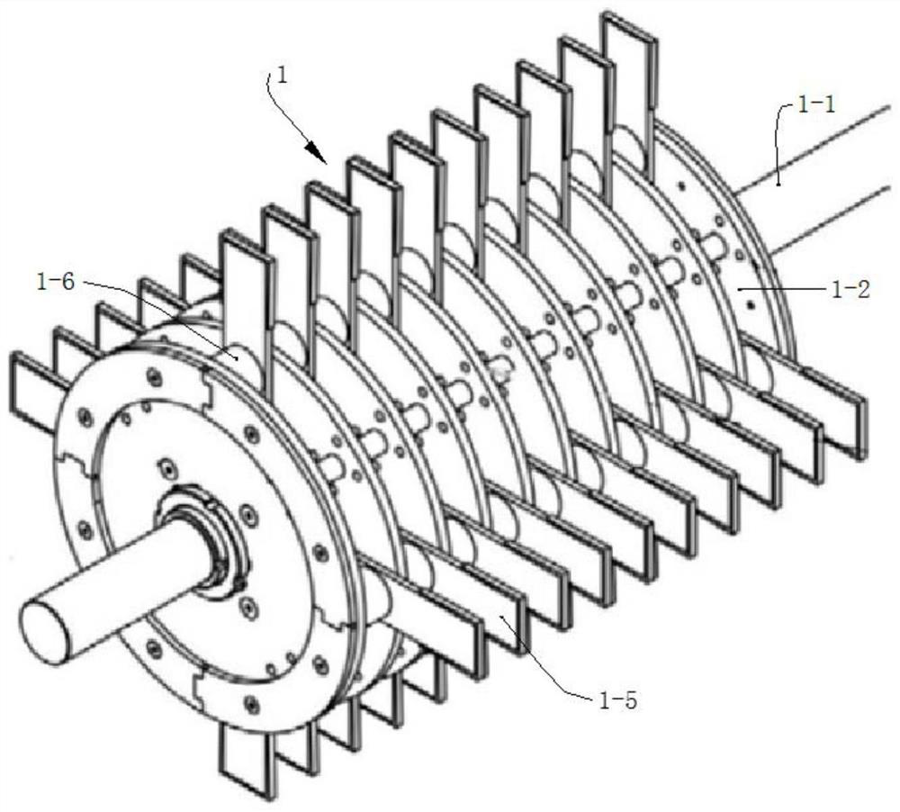
[0063] A fiber recycling machine includes a rotor 1 arranged in a casing 2 .

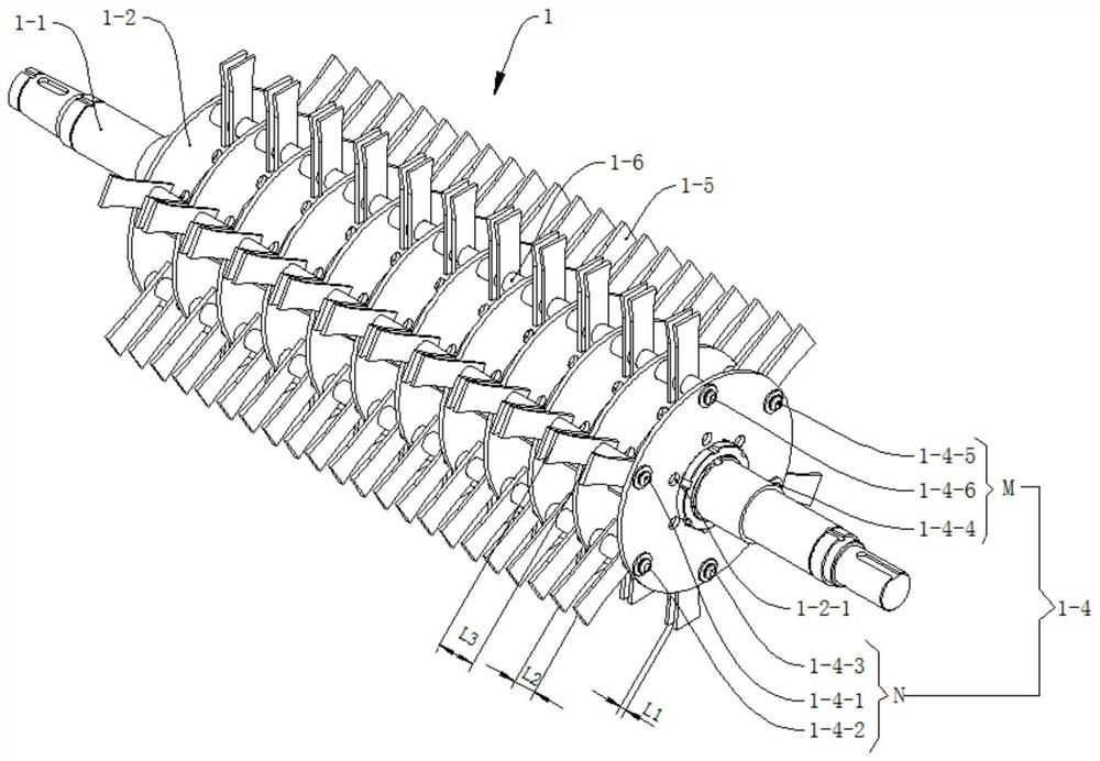
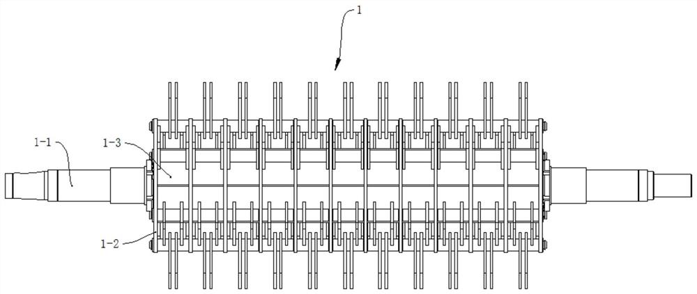
[0064] Such as figure 2 and image 3 As shown, the rotor 1 includes a rotor shaft 1-1, a cutter head 1-2, a shaft pin 1-4, and a blade 1-5.

[0065] Such as figure 2 As shown, there are multiple cutter heads 1-2, and in this embodiment, there are twelve cutter heads 1-2. All cutter heads 1-2 are fixedly mounted on the rotor shaft 1-1 through flat keys or splines. Such as image 3 As shown, a cutterhead spacer 1-3 is installed between two adjacent cutterheads 1-2, and the cutterhead spacer 1-3 is also fixedly installed on the rotor shaft 1-1 through a flat key or a spline. The spacer 1-3 is used to fix the space between two adjacent cutterheads 1-2.

[0066] In order to improve the stability of two adjacent cutterhead spacers 1-3 clamping the cutterhead 1-2, as Figure 4 As shown, a plurality of cutterhead partitions 1-3-1 are welded on the cutterhead spacer 1-3. In this embodiment, three c...


PUM


Abstract

The invention discloses a fiber regeneration machine. The fiber regeneration machine comprising a machine shell, wherein a rotor is arranged in the machine shell and comprises a rotor shaft, cutter heads, shaft pins and blades; the multiple cutter heads are arranged on the rotor shaft; each of the multiple shaft pins is connected with all the cutter heads; all the shaft pins are evenly distributed along the outer rings of the cutter heads; two blades are arranged on the shaft pin located between every two adjacent cutter heads; at least every two adjacent shaft pins form a group; the two blades on the shaft pin, located between every two adjacent cutter heads, in each group of shaft pins gradually approach the cutter heads in the clockwise direction; and the blades, located between every two adjacent cutter heads, on the same shaft pin are arranged in the same mode. According to the fiber regeneration machine, the crushing effect can be improved, the production efficiency is improved, and the energy consumption is reduced.

Description

technical field [0001] The invention relates to the technical field of regeneration equipment, in particular to a fiber regeneration machine. Background technique [0002] When using the recycling machine to shred waste paper, the rotor in the recycling machine is mainly used to cut and shred the waste paper. The crushing effect of waste paper is mainly affected by the structure of the rotor. [0003] Existing rotor 1 structure such as figure 1 As shown, the rotor 1 includes a rotor shaft 1-1, a cutterhead 1-2, a cutterhead spacer ( figure 1 Not shown in), shaft pin ( figure 1 Not shown in), blade 1-5, blade spacer 1-6. A plurality of cutterheads 1-2 and cutterhead spacers for fixing the distance between two adjacent cutterheads 1-2 are installed on the rotor shaft 1-1; Disc 1-2 connection, all shaft pins are evenly distributed along the outer ring of cutter disc 1-2, blades 1-5 are sheathed on the shaft pins between two adjacent cutter discs and used for axially fixing...

Claims


Application Information

Patent Timeline
Patent Type & Authority Applications(China)
IPC IPC(8): B02C18/00B02C18/14B02C18/16B02C18/18B02C18/22B02C18/24B02C23/16B02C23/18
CPCB02C18/0007B02C18/143B02C18/16B02C18/184B02C18/2216B02C18/24B02C23/16B02C23/18B02C2018/0038B02C2018/162
Inventor 张吉祥王玉鹏苗海滨李英杰
Owner SHANDONG JIEFENG MACHINERY MFG
Why Eureka
Try Eureka