
Automatic spraying equipment

A technology of automatic spraying and automatic spraying gun, applied in the direction of spraying device, liquid spraying device, etc., can solve the problems of low production efficiency, overspray, paint waste, etc., achieve the effect of reducing paint waste, improving work efficiency, and improving spray quality

Pending Publication Date: 2021-05-28
SHANGHAI TONGZHOU MACHINERY EQUIP ENGCO
View PDF0 Cites 0 Cited by
  • Summary
  • Abstract
  • Description
  • Claims
  • Application Information

AI Technical Summary

Problems solved by technology

[0007] In view of the shortcomings of the above-mentioned prior art, the purpose of the present invention is to provide an automatic spraying equipment, which is used to solve the problem that the traditional manual spraying method in the prior art cannot quantify and control each spraying process parameter. The product quality can be controlled visually, and the process standardization cannot be achieved, resulting in serious product quality instability. Due to the structural characteristics of the brake disc product, the traditional manual spraying process requires the brake disc product to be turned over many times to complete the spraying, especially the requirements The production efficiency of full-sprayed products is extremely low, because traditional manual spraying cannot accurately adjust the spray gun paint output according to the different film thickness requirements of each plane of the product, resulting in serious overspray and serious paint waste.

Method used


Image

  • Automatic spraying equipment

Examples


Embodiment Construction

[0027] The implementation of the present invention will be illustrated by specific specific examples below, and those skilled in the art can easily understand other advantages and effects of the present invention from the contents disclosed in this specification.

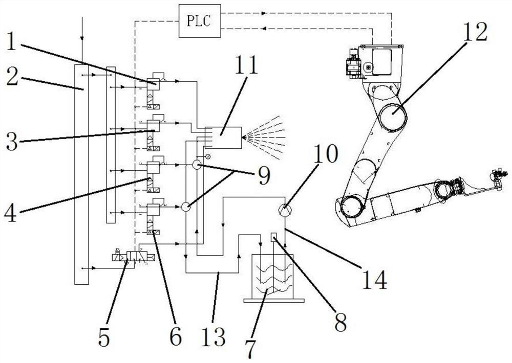
[0028] see figure 1 . It should be noted that the structures, proportions, sizes, etc. shown in the drawings attached to this specification are only used to match the content disclosed in the specification, for those who are familiar with this technology to understand and read, and are not used to limit the implementation of the present invention. Limiting conditions, so there is no technical substantive meaning, any modification of structure, change of proportional relationship or adjustment of size, without affecting the effect and purpose of the present invention, should still fall within the scope of the present invention. The disclosed technical content must be within the scope covered. At the same time, term...


PUM


Abstract

The invention provides automatic spraying equipment, and belongs to the technical field of spraying equipment. The automatic spraying equipment comprises a proportional pressure regulating valve, an air pipeline, a gun opening electromagnetic valve, a PLC, a paint bucket, an automatic spraying gun and a spraying robot, and the automatic spraying gun is installed on a working arm of the spraying robot and connected with the paint bucket through a feeding pipeline and a returning pipeline. The proportional pressure regulating valve comprises a first proportional pressure regulating valve body, a second proportional pressure regulating valve body, a third proportional pressure regulating valve body and a fourth proportional pressure regulating valve body, one side of the gun opening electromagnetic valve is connected with the air pipeline, and the other side of the gun opening electromagnetic valve is connected with the automatic spraying gun. The PLC is separately connected with the first proportional pressure regulating valve body, the second proportional pressure regulating valve body, the third proportional pressure regulating valve body, the fourth proportional pressure regulating valve body, the gun opening electromagnetic valve and the spraying robot through lines. According to the automatic spraying equipment,automatic spraying operation is achieved, the working efficiency of spraying is improved, the labor intensity of operators is reduced, the spraying quality is improved, and the device is simple in structure, and simple and convenient in operation.

Description

technical field [0001] The invention relates to an automatic spraying equipment, which belongs to the technical field of spraying equipment. Background technique [0002] Spraying is a coating method in which a spray gun or a disc atomizer is dispersed into uniform and fine droplets by means of pressure or centrifugal force and applied to the surface of the object to be coated. It can be divided into air spraying, airless spraying, electrostatic spraying and various derived methods of the above basic spraying forms, such as large flow and low pressure atomization spraying, thermal spraying, automatic spraying, multi-group spraying, etc. [0003] The traditional spraying method is artificial spraying, which consists of a compressed air tube and a manual spray gun. [0004] The traditional manual spraying method cannot quantify and control the various spraying process parameters, and only relies on the experience and visual perception of workers to control product quality, an...

Claims


Application Information

Patent Timeline
Patent Type & Authority Applications(China)
IPC IPC(8): B05B7/12B05B7/24B05B13/04B05B12/08B05B12/02B05B15/25
CPCB05B7/1263B05B7/2491B05B13/0431B05B12/084B05B12/02B05B15/25
Inventor 陆通林周文俊汪时君朱伟
Owner SHANGHAI TONGZHOU MACHINERY EQUIP ENGCO
Learn More