Iron plate bending equipment for machining hardware

A technology of iron sheet and hardware, which is applied in the field of iron sheet bending equipment for hardware processing, which can solve the problems of manual retrieving, high risk, low labor intensity of iron sheet bending efficiency, etc.

Pending Publication Date: 2021-05-28
梁康
View PDF1 Cites 7 Cited by
  • Summary
  • Abstract
  • Description
  • Claims
  • Application Information

AI Technical Summary

Problems solved by technology

[0005] In order to overcome the disadvantages of the above-mentioned patents that the handwheel needs to be continuously turned manually when bending the hardware, the efficiency is low, the labor intensity is high, and the materials need to be taken and unloaded manually, which is relatively dangerous. The technical problem to be solved is to provide an iron sheet bending equipment for metal processing that has high bending efficiency, low labor intensity, does not require people to manually put and take materials, and can improve the safety of operators.

Method used


Image

  • Iron plate bending equipment for machining hardware
  • Iron plate bending equipment for machining hardware
  • Iron plate bending equipment for machining hardware

Examples


Embodiment 1

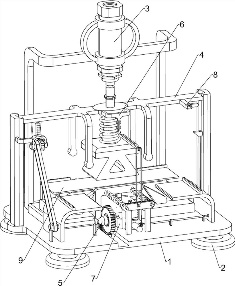
[0029] An iron sheet bending equipment for metal processing, such as Figure 1-2 As shown, it includes a bottom plate 1, a support foot 2, a bending mechanism 3 and a side extrusion mechanism 4, the four corners of the bottom of the bottom plate 1 are connected with support feet 2, and the top rear side of the bottom plate 1 is equipped with a bending mechanism 3 , A side extrusion mechanism 4 is installed between the bottom plate 1 and the bending mechanism 3 .

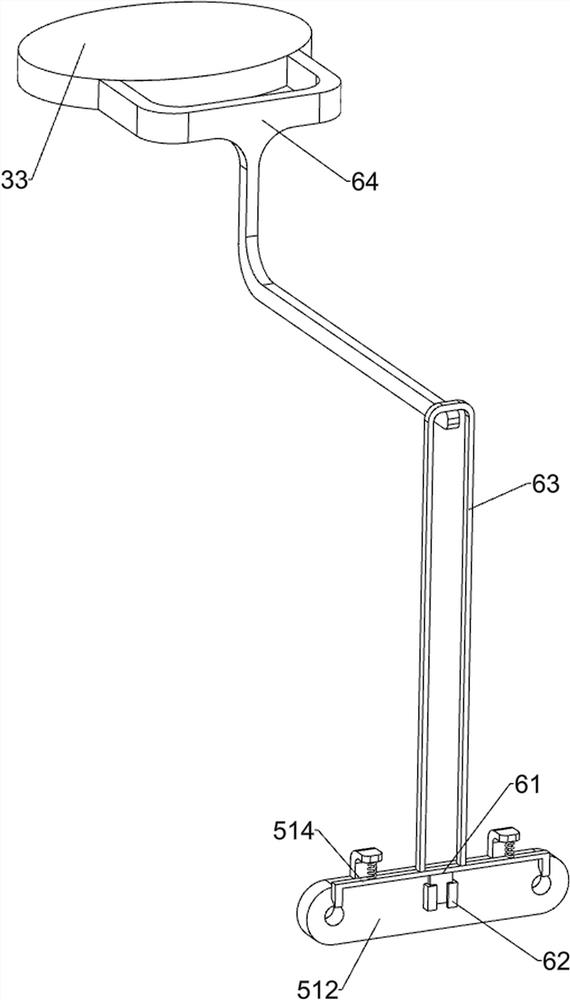
[0030] Bending mechanism 3 includes bracing frame 31, cylinder 32, briquetting block 33, telescoping rod 34, support spring 35, bending block 36 and base 37, bottom plate 1 top rear side is equipped with bracing frame 31, is installed on bracing frame 31 Cylinder 32, the telescoping rod 34 of cylinder 32 is connected with briquetting 33, and the bottom of briquetting 33 is connected with telescoping rod 34, and the bottom of telescoping rod 34 is connected with bending block 36, is connected with support between bend...

Embodiment 2

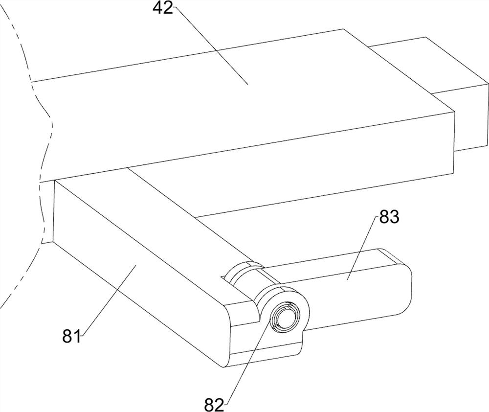
[0034] On the basis of Example 1, such as Figure 3-4Shown, also include pusher mechanism 5, pusher mechanism 5 includes placement plate frame 51, elastic ratchet bar 52, first connecting frame 53, ratchet gear 54, transmission belt set 55, transmission shaft 56, one-way clutch 57, transmission gear 58, rack frame 59, push plate frame 510, guide bar 511, second fixed plate 512, second back-moving spring 513, elastic bayonet frame 514 and limit frame 515, the left and right sides of base plate 1 front portion The sides are all connected with a place plate frame 51, the bottom of the push rod frame 42 on the left side is connected with an elastic ratchet bar 52, and the guide rail frame 41 on the left side is connected with a first connecting frame 53, which is connected in a rotational manner on the first connecting frame 53. There is a ratchet gear 54, and the ratchet gear 54 cooperates with the elastic ratchet rack 52, and a drive shaft 56 is rotatably connected to the left s...

Embodiment 3

[0039] On the basis of Example 2, such as Figure 5-7 Shown, also includes unloading mechanism 7, and unloading mechanism 7 includes fixed seat 71, sliding connection block 72, the 3rd return spring 73, wedge-shaped push block 74, baffle plate 75, elastic push block 76, fixed rod 77, Inclined plane frame 78, latch 79, the 4th back-moving spring 710, connecting rod 711 and guide sleeve 712, the front side middle part of base plate 1 is connected with fixed seat 71, is connected with sliding connection block 72 slidingly on the fixed seat 71, the sliding connection block 72 is connected with the 3rd back-moving spring 73 between fixed seat 71, and the rear end of sliding connection block 72 is connected with wedge-shaped pushing block 74 slidingly, and the front side of base 37 has oblique chute, and wedge-shaped pushing block 74 and base 37 The inclined chute of sliding fit, the top of sliding connection block 72 is connected with baffle plate 75, the bottom of push plate frame...


PUM


Abstract

The invention relates to bending equipment and particularly relates to iron plate bending equipment for machining hardware. The technical problem solved by the invention is to provide iron plate bending equipment for machining hardware. The iron plate bending equipment for machining hardware is high in iron plate bending efficiency and low in labor intensity; the materials do not need to be manually placed and taken by people; and the operation safety of operators can be improved. In order to solve the technical problem, the invention provides the iron plate bending equipment for machining hardware. The iron plate bending equipment comprises a bottom plate, a bending mechanism and a side extrusion mechanism, wherein the bottom of the bottom plate is connected with supporting legs; the bending mechanism is mounted on the bottom plate; and the side extrusion mechanism is mounted between the bottom plate and the bending mechanism. According to the iron plate bending equipment for machining hardware, iron plates can be bent and formed through the bending mechanism and the side extrusion mechanism; one-time forming is achieved; and the bending efficiency is high.

Description

technical field [0001] The invention relates to a bending equipment, in particular to an iron sheet bending equipment for metal processing. Background technique [0002] After searching, the patent publication number is: CN210412027U patent, which discloses a bending machine for hardware processing, including a rectangular base plate; a first inverted L-shaped folding plate is fixed on one side of the upper surface of the rectangular base plate, and the The upper surface of the rectangular base plate is fixed with a folding plate mold base by bolts; the folding plate mold base is slidingly fitted with a folding plate pressing head assembly through a plurality of first cylinders; the upper end surface of the folding plate pressing head assembly is in contact with the first inverted L-shaped The pressure assembly is fixed by bolts between the lower sides of the folded plate; the folded plate mold base includes a base plate of the mold base and a rectangular support plate that ...

Claims


Application Information

Patent Timeline
Patent Type & Authority Applications(China)
IPC IPC(8): B21D5/01B21D45/02B21D43/02
CPCB21D5/01B21D43/02B21D45/02
Inventor 梁康
Owner 梁康
Why Eureka
Try Eureka