New energy automobile part forging and pressing machining device
A technology for new energy vehicles and processing devices, applied in forging/pressing/hammer devices, forging presses, forging presses, etc., can solve the problems of forging deviation, inconvenience of precise control of included angle, inconvenience, etc., and achieve the effect of reducing deviation.
- Summary
- Abstract
- Description
- Claims
- Application Information
AI Technical Summary
Problems solved by technology
Method used
Image

Examples
Embodiment 1
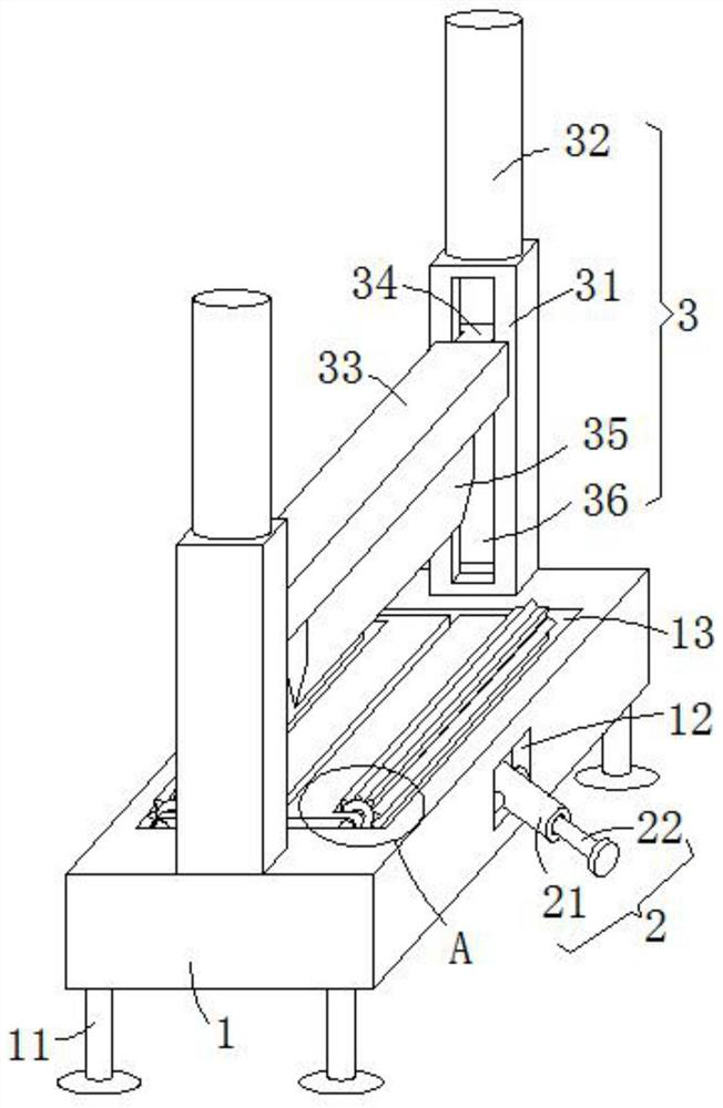
[0021] see Figure 1-3 , this embodiment provides a new energy automobile parts forging processing device, including a processing table 1, the four corners of the bottom surface of the processing table 1 are vertically provided with supporting legs 11, and the processing table 1 is used to place and support Forged auto parts, by setting support legs 11, it is convenient to support the entire processing table 1. The upper end surface of the processing table 1 is provided with a forging mechanism 3. The forging mechanism 3 includes two adjustment support columns 31, two hydraulic cylinders 32 and adjustment The crossbeam 33 and two adjustable support columns 31 are vertically welded on the front and rear sides of the upper end of the processing table 1, and the opposite side walls are provided with T-shaped adjustment grooves 36, and the hydraulic cylinder 32 is vertically arranged on the upper end surface of the adjustment support column 31, and the hydraulic pressure The tip o...
Embodiment 2
[0031] see image 3 , further improvements have been made on the basis of Example 1:
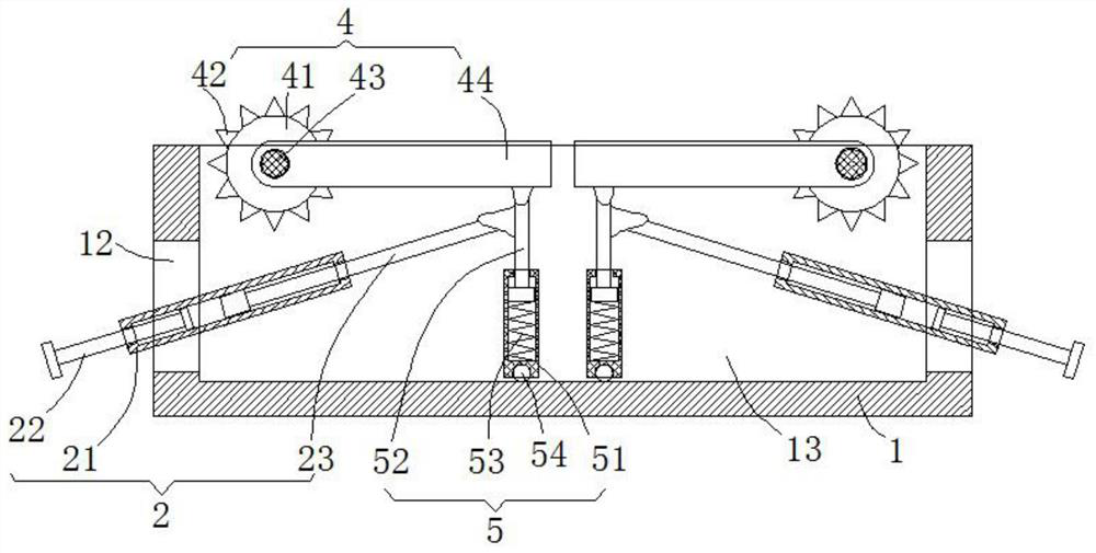
[0032] In order to solve the problem of how to assist the horizontal movement of the entire buffer mechanism 5, the center position of the bottom end of the buffer sleeve 51 is rotated and embedded with a rotating ball 54 that can slide freely on the inner bottom surface of the rectangular buffer groove 13. The end is embedded with a rotating ball 54, so that the rotating ball 54 can slide freely on the bottom end surface of the rectangular buffer groove 13, which is convenient to assist the horizontal movement of the entire buffer mechanism 5 and reduce the sliding friction when the entire buffer mechanism 5 moves horizontally.
PUM
 Abstract
Description
Claims
Application Information
PatSnap Eureka turns technology decisions into work you can execute. Powered by our Innovation Knowledge Graph, it runs expert workflows across engineering, life sciences, materials and intellectual property. Get your review-ready output in minutes.


