Spot welding machine for switch production

A spot welding machine and switch technology, which is applied in welding equipment, resistance welding equipment, resistance electrode holders, etc., and can solve problems such as misstepping and working errors

Inactive Publication Date: 2021-05-28
陈鼎双
View PDF7 Cites 0 Cited by
  • Summary
  • Abstract
  • Description
  • Claims
  • Application Information

AI Technical Summary

Problems solved by technology

[0003] When the existing spot welding machine is in use, because it is started by the pedal, it may be accidentally stepped on due to foot shaking or mistakes at the beginning of work, resulting in work errors

Method used


Image

  • Spot welding machine for switch production
  • Spot welding machine for switch production
  • Spot welding machine for switch production

Examples


Embodiment 1

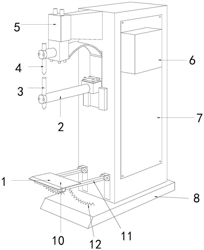
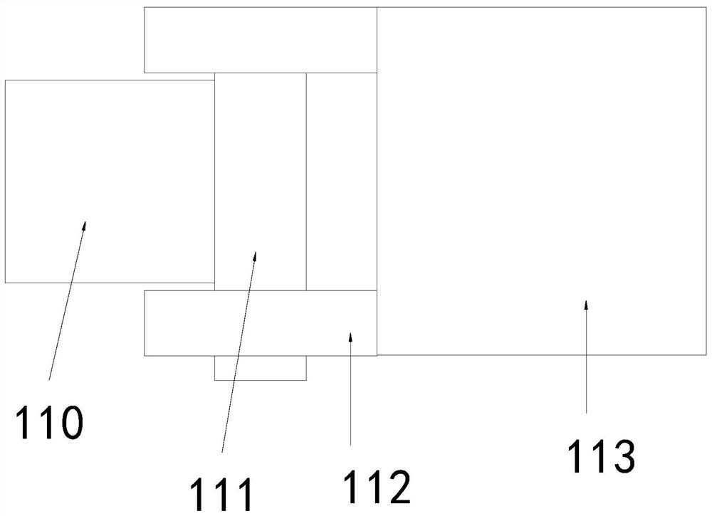
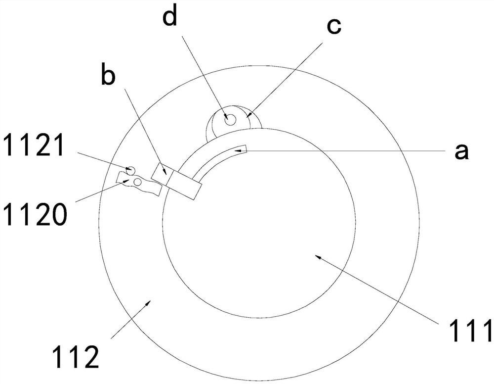
[0028] see Figure 1-6 , the present invention provides a technical scheme of a spot welding machine for switch production: its structure includes a pedal 1, an arm 2, a lower electrode 3, an upper electrode 4, a cylinder body 5, a controller 6, a box body 7, and a bottom plate 8. The top surface of the bottom plate 8 is connected to the bottom of the box body 7, the side of the box body 7 is connected to the controller 6, the front side of the box body 7 is equipped with a support arm 2, and the tail end of the support arm 2 is provided with a lower electrode 3, An upper electrode 4 is arranged above the lower electrode 3, and the upper electrode 4 is connected to a cylinder body 5. The cylinder body 5 is connected to the front side of the box body 7, and a pedal 1 is arranged on the front side bottom of the box body 7. The pedal 1 includes a plate body 10, a pole 11, and a spring 12. The plate body 10 is connected to the bottom of the front side of the box body 7 through the...

Embodiment 2

[0031] see Figure 1-6 , the present invention provides a technical scheme of a spot welding machine for switch production: its structure includes a pedal 1, an arm 2, a lower electrode 3, an upper electrode 4, a cylinder body 5, a controller 6, a box body 7, and a bottom plate 8. The top surface of the bottom plate 8 is connected to the bottom of the box body 7, the side of the box body 7 is connected to the controller 6, the front side of the box body 7 is equipped with a support arm 2, and the tail end of the support arm 2 is provided with a lower electrode 3, An upper electrode 4 is arranged above the lower electrode 3, and the upper electrode 4 is connected to a cylinder body 5. The cylinder body 5 is connected to the front side of the box body 7, and a pedal 1 is arranged on the front side bottom of the box body 7. The pedal 1 includes a plate body 10, a pole 11, and a spring 12. The plate body 10 is connected to the bottom of the front side of the box body 7 through the...


PUM


Abstract

The invention discloses a spot welding machine for switch production, which structurally comprises a pedal, a support arm, a lower electrode, an upper electrode, a cylinder body, a controller, a box body and a bottom plate; the top surface of the bottom plate is connected with the bottom of the box body, the side surface of the box body is connected with the controller, the support arm is mounted on the front side of the box body, the lower electrode is arranged at the tail end of the support arm, the upper electrode is arranged above the lower electrode, the upper electrode is connected with the cylinder body, the cylinder body is connected to the front side of the box body, and the pedal is arranged at the bottom of the front side of the box body; and the pedal comprises a pedal body, supporting rods and a spring, the pedal body is connected to the bottom of the front side of the box body through the supporting rods, and the bottom of the pedal body is connected with the bottom plate through the spring. The spot welding machine has the beneficial effects that through the design of the spot welding machine, the pedal needs to be treaded for starting before use, therefore, an operator has an opportunity of mistakenly treading, and work errors caused by mistakenly treading at the beginning are avoided.

Description

technical field [0001] The invention relates to the field of spot welding machines, in particular to a spot welding machine for switch production. Background technique [0002] The spot welding machine adopts the principle of double-sided double-point overcurrent welding. When working, two electrodes pressurize the workpiece so that the two layers of metal form a certain contact resistance under the pressure of the two electrodes, and the welding current flows from one electrode to the other. Instantaneous thermal fusion is formed at the two contact resistance points, and the welding current flows from the other electrode along the two workpieces to this electrode to form a loop, and will not damage the internal structure of the workpiece to be welded. [0003] When the existing spot welding machine is in use, since it is started by pedals, when it just starts to work, it may be accidentally stepped on due to foot shaking or mistakes, resulting in work errors. Contents of ...

Claims


Application Information

Patent Timeline
Patent Type & Authority Applications(China)
IPC IPC(8): B23K11/11B23K11/31B23K11/36
CPCB23K11/115B23K11/31B23K11/36
Inventor 柳瑞林
Owner 陈鼎双
Why Eureka
Try Eureka