
Machining tool for missile shell and clamping method of machining tool

A shell and missile technology, which is applied in the direction of metal processing equipment, metal processing machinery parts, clamping, etc., can solve the problems that the processing accuracy cannot be guaranteed, and ordinary tooling is difficult to clamp stably, so as to ensure stable clamping and reduce the workpiece Vibration, the effect of improving machining accuracy

Inactive Publication Date: 2021-05-28
SICHUAN FUTURE AEROSPACE IND LLC
View PDF12 Cites 1 Cited by
  • Summary
  • Abstract
  • Description
  • Claims
  • Application Information

AI Technical Summary

Problems solved by technology

[0005] The purpose of the invention is to provide a processing tool for a missile shell and its Clamping method

Method used


Image

  • Machining tool for missile shell and clamping method of machining tool
  • Machining tool for missile shell and clamping method of machining tool
  • Machining tool for missile shell and clamping method of machining tool

Examples


Embodiment 1

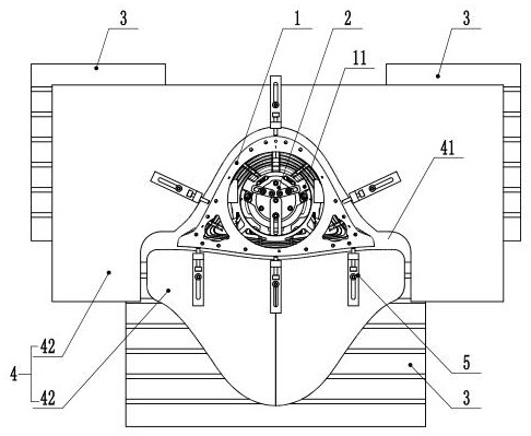
[0043] Such as figure 1 , figure 2and Figure 6 As shown, in this embodiment, a kind of tooling for processing a missile casing includes a pressing mechanism 2 and a top tightening mechanism;

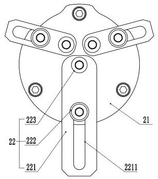
[0044] The pressing mechanism 2 includes a base 21 and a pressing part 22 arranged on the base 21, the base 21 is used to be arranged in the cavity at the bottom of the missile housing 1, and the pressing part 22 is used to press on the Ribs on the inner cavity of the missile casing 1;

[0045] The tightening mechanism includes a supporting component and a tightening component arranged on the supporting component, and the tightening component is used to push the missile casing 1 from the surrounding wall.

[0046] Fix the pressing mechanism 2 and the processing platform, and place the missile housing 1 to be processed on the position of the pressing mechanism 2, so that the pressing mechanism 2 is embedded in the inner cavity of the lower part of the missile housing 1, and adjust th...

Embodiment 2

[0053] Such as Figure 1-Figure 6 As shown, the present invention also discloses a missile shell clamping method, using the above-mentioned missile shell processing tool to clamp the missile shell, the steps are as follows:

[0054] A, the base 21 is installed on the processing platform;

[0055] B, hoisting the missile casing 1 to be processed on the processing platform, so that the base 21 on the processing platform is embedded in the missile casing 1 from the lower end of the missile casing 1;

[0056] C. Operate the pressing part on the base 21 through the operating tool 6, so that the pressing part compresses the rib plate 11 on the inner wall of the missile casing 1;

[0057] D. A tightening mechanism is arranged around the missile casing 1, and the missile casing 1 is tightened from the peripheral wall of the missile casing 1 through the tightening parts in the tightening mechanism.

[0058] Specifically, the operating tool 6 includes a handle 61, and an operating par...

Embodiment 3

[0062] Such as Figure 5 As shown, in this embodiment, the difference from Embodiment 2 is that the operating part 62 includes a magnetic part, and the magnetic part can absorb the pressing plate 221 in the pressing unit 22, so as to rotate and stretch the pressing plate 221 through the handle 61, The pressure plate 221 overlaps the rib plate 11 on the inner wall of the missile casing 1 .

[0063] Further, the magnetic component is an electromagnet, and the electromagnet not only has a strong adsorption capacity, but also has a controllable suction force and is more convenient to operate.


PUM


Abstract

The invention relates to the technical field of machining, in particular to a machining tool for a missile shell and a clamping method of the machining tool. The tool comprises a pressing mechanism and a jacking mechanism. The pressing mechanism comprises a base and a pressing part arranged on the base, the base is used for being arranged in a cavity in the lower portion of the missile shell, and the pressing part is used for being pressed on a rib plate in an inner cavity of the missile shell. The jacking mechanism comprises a supporting component and a jacking component arranged on the supporting component, and the jacking component is used for pushing the missile shell in the circumferential direction of the outer wall of the missile shell. The pressing mechanism is embedded into an inner cavity of the lower portion of the missile shell, the lower portion of the missile shell is pressed on a machining platform, then the jacking component is supported to the position of the upper portion of the missile shell through the supporting component, and the upper portion of the missile shell is jacked from the peripheral wall of the missile shell through the jacking component on the supporting component, so that stable clamping of the missile shell is achieved, and the machining precision of the inner wall of the upper portion of the missile shell is guaranteed.

Description

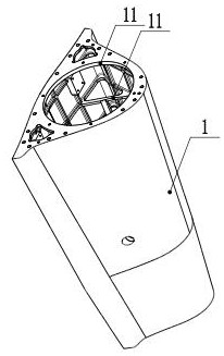
technical field [0001] The invention relates to the technical field of mechanical processing, in particular to a processing tool for a missile casing and a clamping method thereof. Background technique [0002] Aviation and aerospace parts often adopt thin-walled special-shaped structures, the purpose is to reduce weight, reduce energy consumption of aircraft during flight, and exert its super capabilities. High precision, difficult clamping, and difficult processing are the main characteristics of this type of parts processing, so it is necessary to design special tooling to achieve stable clamping of parts. [0003] Such as figure 1 Shown is a missile shell. The blank material of the missile shell is ZL114A sand casting, which is a typical thin-walled frame part. The outer wall of the shell is smooth, and there are several ribs on the inner wall. The length of the shell is 1m-1.5m. Has a big endian and a little endian of different sizes. Since there is no process boss f...

Claims


Application Information

Patent Timeline
IPC IPC(8): B23Q3/06B23Q3/154
CPCB23Q3/062B23Q3/1543
Inventor 谢长敏张宇梁朝文王萍黄小佳郭小波周波任晓艳谭文川陈海方段晓丹
Owner SICHUAN FUTURE AEROSPACE IND LLC
Learn More