Film continuous punching tool and its punching process

A technology of film and tooling, which is applied in the field of film continuous punching tooling and its punching technology, can solve the problems of manual punching troubles, etc., and achieve the effect of improving punching efficiency and facilitating transmission and winding

Active Publication Date: 2022-01-28
萨固密渝锦(重庆)橡塑制品有限公司 +2
View PDF6 Cites 0 Cited by
  • Summary
  • Abstract
  • Description
  • Claims
  • Application Information

AI Technical Summary

Problems solved by technology

[0004] Aiming at the deficiencies in the prior art, the present invention provides a film continuous punching tool and its punching process to solve the troublesome problem of manual punching

Method used


Image

  • Film continuous punching tool and its punching process
  • Film continuous punching tool and its punching process
  • Film continuous punching tool and its punching process

Examples


Embodiment 1

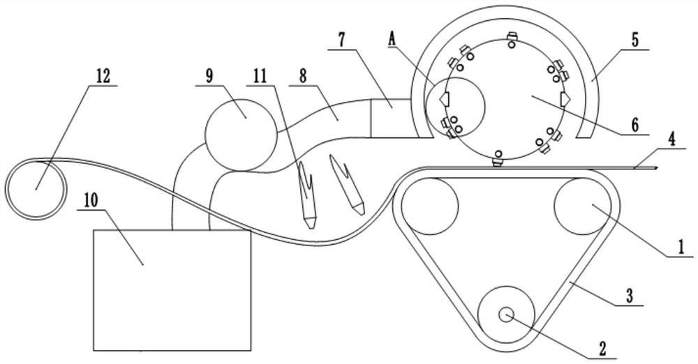
[0017] Such as figure 1 As shown, the film continuous punching tool includes a frame, and the frame is provided with a transmission mechanism, a punching mechanism, a dust removal mechanism and a cooling mechanism. The transmission mechanism includes three transmission wheels 1 that are rotatably connected to the frame. The wheels 1 are distributed in a triangle. Specifically, the three transmission wheels 1 are distributed in an inverted isosceles triangle. The outer sides of the three transmission wheels 1 are provided with a conveyor belt 3. A motor A for driving one of the transmission wheels 1 to rotate is fixed on the frame. , the output shaft of the motor A is fixed to the transmission wheel 1, and the transmission wheel 1 drives the other two transmission wheels 1 to move through the transmission belt 3 to realize the transmission of the transmission belt 3. During actual use, in order to ensure transmission stability, the transmission wheel 1 can be selected for use w...

Embodiment 2

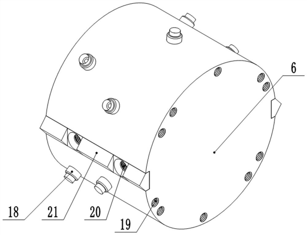
[0032] The difference between this embodiment and embodiment 1 is that, in combination with Figure 4 As shown, the dust suction fan 9, the cooling fan and the collection box 10 are not provided. Specifically, the drum 6 is coaxially fixed with a cam 22, and two piston barrels 27 are symmetrically fixed above and below the cam 22 on the frame. The barrel 27 is vertically slidably connected with a piston 24, the piston 24 is fixed with a piston rod 23, and one end of the piston rod 23 stretches out from the piston barrel 27 and is slidably connected with the outer wall of the cam 22, and the cam 22 and the piston rod 23 form a cam mechanism. 22 rotations drive the piston rod 23 to slide vertically. The sealing end of the piston barrel 27 is provided with an air inlet 28 and an air outlet 29, the air inlet 28 communicates with the dust suction pipe 8, the air outlet 29 communicates with the blowing pipe 11, and the air inlet 28 is equipped with a gas unidirectionally entering th...


PUM


Abstract

The invention belongs to the technical field of sealing strip processing, and specifically discloses a film continuous punching tool and its punching process, including a frame, on which a punching mechanism and a transmission mechanism are arranged, and the transmission mechanism is used to transmit the film to be punched. The film, the punching mechanism is located above the transmission mechanism, the punching mechanism includes a rotating cylinder connected to the frame, the outer wall of the rotating cylinder is evenly distributed with multiple groups of punching components along the circumference, the punching components include punching parts and shearing parts, punching The hole piece includes a punching nail detachably connected to the outer wall of the drum. The punching nail includes a mounting part for connecting with the drum and a punching part for punching holes. The punching part is in the shape of a ring; the shearing part includes The connecting part for connecting with the outer wall of the drum and the shearing part for cutting the film, the length direction of the connecting part is parallel to the axial direction of the drum, and the shearing part includes several triangular prism-shaped shears distributed along the length direction of the connecting part. Cutting blocks, with spacing between adjacent cutting blocks. By adopting the scheme of the invention, the problem of continuous punching of the film can be solved.

Description

technical field [0001] The invention belongs to the technical field of sealing strip processing, and in particular relates to a film continuous punching tool and a punching process thereof. Background technique [0002] At present, the two ends of the sealing strip (car door frame products) need to be connected after the processing is completed, so that the sealing strip forms a ring shape. In order to obtain a better docking effect, a film is usually set at the joint of the sealing strip, and the film is vulcanized Fix with the end of the sealing strip. Because most of the sealing strips are bubble tube products, it is easy to deform when the car door is opened and closed. In order to avoid gas blockage when the sealing strip is deformed, it is necessary to open a through hole on the film that communicates with the inner cavity of the sealing strip. [0003] In the prior art, punching holes on the film is usually done manually by directly pressing the film through a circul...

Claims


Application Information

Patent Timeline
Patent Type & Authority Patents(China)
IPC IPC(8): B26D7/02B08B5/04
CPCB26D7/02B08B5/04
Inventor 范长阳丁灵段柏均杨天兵
Owner 萨固密渝锦(重庆)橡塑制品有限公司
Why Eureka
Try Eureka