
Wall surface punching drilling machine for building decoration and using method

A technology for construction and drilling rigs, applied in stone processing tools, work accessories, manufacturing tools, etc., can solve the problems of enlarged hole diameter, troublesome cleaning, and limited wire length, so as to avoid follow-up troubles, troublesome cleaning, and wires winding effect

Pending Publication Date: 2021-05-28
铜陵职业技术学院
View PDF0 Cites 1 Cited by
  • Summary
  • Abstract
  • Description
  • Claims
  • Application Information

AI Technical Summary

Problems solved by technology

[0003] The existing drilling machine used by the decoration workers sprays the dust directly to the decoration workers when they are drilling, and splashes to the decoration workers' eyes to cause damage. Inhaling a large amount of dust is easy to cause inflammation of the trachea. It will be contaminated with a lot of dust, and the follow-up cleaning is more troublesome. At the same time, the drilling machines for decoration in the prior art are all plugged into the power socket through wires and plugs, and the length of the wires is limited. Traction or winding increases the difficulty of drilling for the operator, which is very inconvenient. At the same time, the drilling machines in the prior art are often unable to control the drilling depth very well. The depth of the hole is controlled according to the experience of the decoration workers. , When the hole depth is not enough, you need to drill again, which will enlarge the diameter of the hole and affect the installation stability of the installation accessories. If the hole is too deep, it will easily reduce the service life of the drill bit.

Method used


Image

  • Wall surface punching drilling machine for building decoration and using method
  • Wall surface punching drilling machine for building decoration and using method
  • Wall surface punching drilling machine for building decoration and using method

Examples


Embodiment Construction

[0027]In order to make the purpose, technical solutions and advantages of the embodiments of the present invention clearer, the technical solutions in the embodiments of the present invention will be clearly and completely described below in conjunction with the drawings in the embodiments of the present invention. Obviously, the described embodiments It is a part of embodiments of the present invention, but not all embodiments. Based on the embodiments of the present invention, all other embodiments obtained by persons of ordinary skill in the art without creative efforts fall within the protection scope of the present invention.

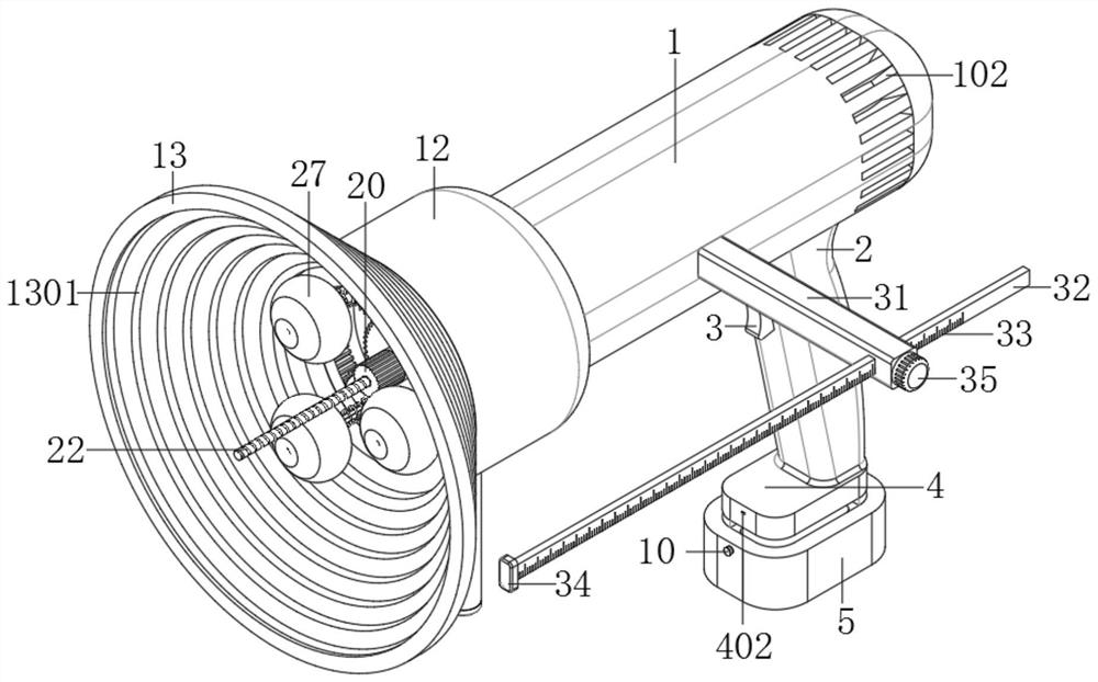
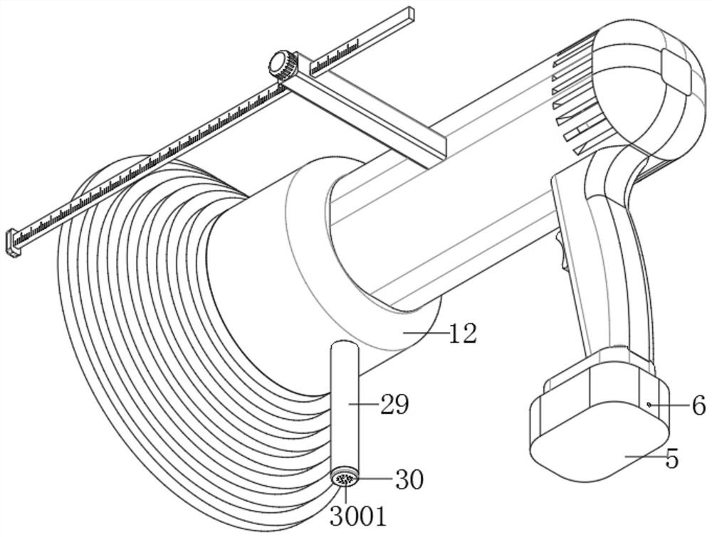
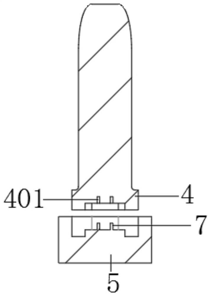
[0028] see Figure 1-7 , a wall drilling machine for building decoration and its use method, comprising a fuselage 1, a motor bracket 14 and a sealed bearing 18, a handle 2 is provided at the bottom right side of the fuselage 1, and a starter is provided at the upper end of the left side of the handle 2 The button 3 and the bottom end of the handl...


PUM


Abstract

The invention relates to the field of building decoration related equipment, in particular to a wall surface punching drilling machine for building decoration and a using method. The wall surface punching drilling machine comprises a machine body, motor supports and a sealing bearing, a grip is arranged at the bottom end of the right side of the machine body, a starting button is arranged at the upper end of the left side of the grip, and a base is fixedly connected to the bottom end of the grip. A storage battery assembly is inserted into the bottom end of the base, a mounting cavity is formed in the machine body, a mounting cover is fixedly connected to the outer wall of the left end of the machine body, a funnel-shaped rubber dust collection cover is fixedly clamped to the left end of the mounting cover, and a plurality of dust collection grooves are evenly formed in the inner wall of the funnel-shaped rubber dust collection cover. Motors are fixedly mounted on the inner wall of the right side of the mounting cavity through the multiple sets of motor supports which are evenly distributed in a radial shape, and the output ends of the left sides of the motors are fixedly connected with a driving shaft. According to the punching drilling machine, decoration work operation is facilitated, dust can be well collected and cleaned, and meanwhile the punching depth can be well controlled.

Description

technical field [0001] The invention relates to the field of equipment related to building decoration, in particular to a wall drilling machine for building decoration and a use method thereof. Background technique [0002] In the process of house decoration, it is necessary to install various lighting and pendants, as well as water pipes and lines. When installing lighting, pendants, water pipes and lines, it is necessary to drill holes on the wall, so the wall drilling machine is a must in the process of building decoration. One of the indispensable equipment. [0003] The existing drilling machine used by the decoration workers sprays the dust directly to the decoration workers when they are drilling, and splashes to the decoration workers' eyes to cause damage. Inhaling a large amount of dust is easy to cause inflammation of the trachea. It will be contaminated with a lot of dust, and the follow-up cleaning is more troublesome. At the same time, the drilling machines fo...

Claims


Application Information

Patent Timeline
Patent Type & Authority Applications(China)
IPC IPC(8): B28D1/14B28D7/00B28D7/02
CPCB28D1/14B28D7/005B28D7/00B28D7/02
Inventor 王文璟
Owner 铜陵职业技术学院
Learn More