Simple injection molding pipe fitting shearing device
A technology of shearing device and injection molding tube, which is applied in metal processing and other directions, can solve the problems of time-consuming and labor-intensive, easy damage of scissors, etc., and achieve the effect of saving collection process, improving efficiency and saving manpower
- Summary
- Abstract
- Description
- Claims
- Application Information
AI Technical Summary
Problems solved by technology
Method used
Image

Examples
Embodiment 1
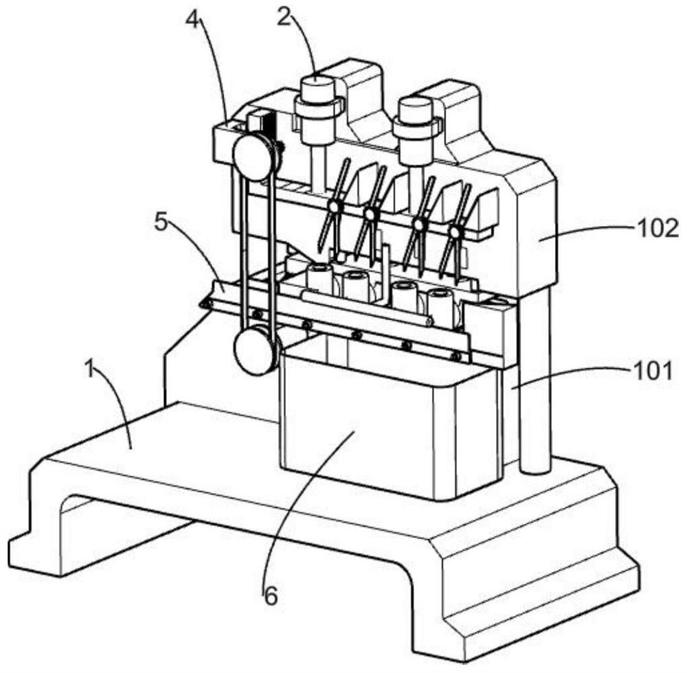
[0045] A simple shearing device for injection molding pipe fittings, such as Figure 1-4 As shown, it includes a bracket 1, a slide rail plate 101, a fixed plate 102, a shearing mechanism, a clamping mechanism, a pushing mechanism, a slide rail 5 and a material box 6, the slide rail plate 101 is fixedly installed on the bracket 1, and the fixed plate 102 is fixedly connected with the slide rail plate, the shearing mechanism is fixedly installed on the upper right side of the front part of the bracket 1, the clamping mechanism is slidingly connected with the lower right side of the slide rail plate 101, and the pushing mechanism is connected with the middle of the front part of the bracket 1 on the right side , part of the pushing mechanism is located below the clamping mechanism, the slide rail 5 is fixedly installed on the lower side of the groove in the middle of the bracket 1, the slide rail 5 is slidingly connected with the pushing mechanism, and the two material boxes 6 ar...
Embodiment 2
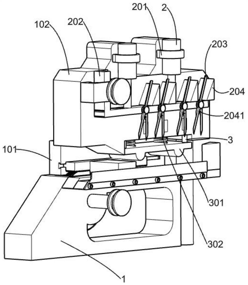
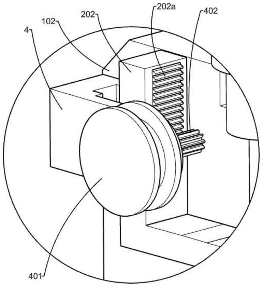
[0048] On the basis of Example 1, such as Figure 2-4 As shown, the shearing mechanism includes a fixed ring 201, a cylinder 2, an L-shaped frame 202, a bar gear 202a, a cutter 203, an inclined block 204 and a first spring 2041, and the two fixed rings 201 are fixedly mounted on the fixed ring 201 respectively. The upper middle position and the right side of the front part, the two cylinders 2 are fixedly installed inside each fixed ring 201, the L-shaped frame 202 is fixedly installed at the lower ends of the telescopic rods of the two cylinders 2, and the bar gear 202a is fixedly installed On one side of the vertical direction of the L-shaped frame 202, there are four pairs of cutters 203, and the four pairs of cutters are evenly distributed on the front side of the plate placed in the horizontal direction of the L-shaped plate, and the longer cutters 203 in each pair of cutters Fixedly installed on the front side of the plate placed in the horizontal direction of the L-shap...
Embodiment 3
[0055] On the basis of Example 2, such as figure 2 As shown, the elastic member is set as a second spring 302 , the second spring 302 acts on the pressing plate 301 , and the second spring 302 gives the pressing plate 301 a downward force.
[0056] The elastic member is set as the second spring 302, and when the clamping mechanism clamps the injection molded pipe, the existence of the second spring 302 plays a certain buffering role, ensuring that the injection molded part is not easily damaged.
PUM
 Abstract
Description
Claims
Application Information