Spring compression conveying device

A conveying device and conveyor belt technology, which is applied in the direction of conveyors, conveyor objects, transportation and packaging, etc., can solve the problem of increasing friction between conveyor belts/conveyor chains and baffles, easily damaged conveyor belts/conveyor chains, pulleys/ Problems such as the inability of the sprocket to rotate, to achieve the effect of improving the tension effect, simplifying the structure, and reducing shedding

Pending Publication Date: 2021-05-28
FOSHAN QILIN MATTRESS MACHINERY CO LTD
View PDF0 Cites 0 Cited by
  • Summary
  • Abstract
  • Description
  • Claims
  • Application Information

AI Technical Summary

Problems solved by technology

[0005] However, the existing compression conveying device has obvious disadvantages: 1. The length of the inclined compression structure is long, which is not conducive to rapid production; 2. In the process of compressing and conveying, the spring will tightly press the conveyor belt / conveyor chain of the conveying device On the baffle, this will greatly increase the friction between the conveyor belt / conveyor chain and the baffle, and it will easily damage the conveyor belt / conveyor chain after long-term use
[0006] In view of these problems, there is an existing compression conveying device, the compression section of which is composed of several pulleys / sprockets, thereby avoiding the use of baffles, and then this structure needs to install multiple pulleys / sprockets, and ensure that the pulleys / chains The pulley is tightly connected to the conveyor belt / chain, so the structure is complex. At the same time, the compression force of the spring will easily cause the pulley / sprocket to be tightly pressed against the conveyor belt / chain, which will cause the pulley / sprocket to fail to rotate, which is very dangerous.

Method used


Image

  • Spring compression conveying device
  • Spring compression conveying device
  • Spring compression conveying device

Examples


Embodiment Construction

[0025] Aiming at the deficiencies of the prior art, the present invention aims to provide a spring compression conveying device.

[0026] To achieve the above object, the present invention adopts the following technical solutions:

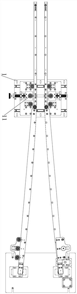
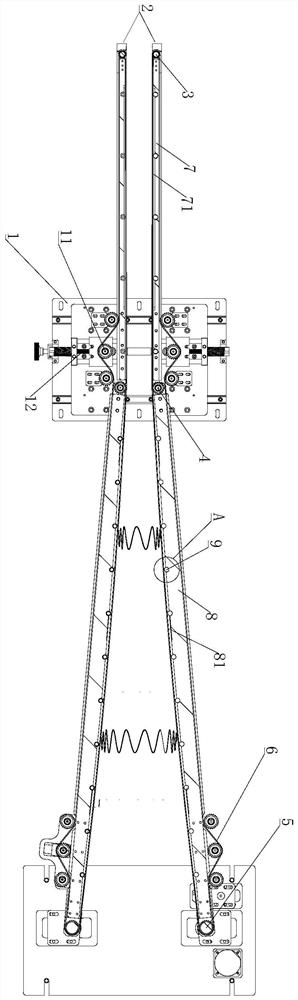
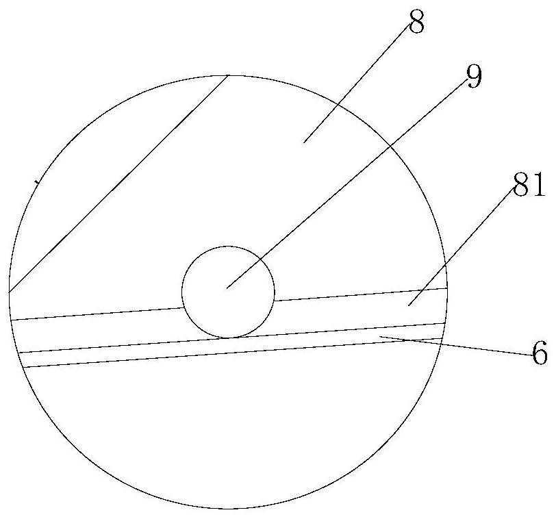
[0027] A spring compression conveying device, comprising a chassis 1 and a conveying mechanism 2, the two conveying mechanisms 2 are arranged oppositely, and the conveying mechanism 2 is formed by winding a section of conveying belt / conveying chain 6, and the conveying belt / conveying chain 6 constitute a flat delivery section 21 and an arc section 22, the arc section 22 is in a convex arc shape, the output end of the arc section 22 is tangent to the input end of the flat delivery section 21, and the flat delivery section Section 21 and circular arc section 22 are not provided with baffle plate, and some columns 9 are all arranged in described flat delivery section 21 and circular arc section 22. The chains 6 are all wound on the uprights 9 , and t...


PUM


Abstract

The invention discloses a spring compression conveying device. The spring compression conveying device comprises a bottom frame and conveying mechanisms, wherein the two conveying mechanisms are oppositely arranged, each conveying mechanism is composed of a flat conveying section and an arc section which are not provided with baffles, and a plurality of stand columns are arranged in each flat conveying sections and each arc section. According to the spring compression conveying device, firstly, the stand columns are arranged to replace original baffles, and the conveying belts / conveying chains are in point contact with the stand columns, so that the friction resistance generated in the moving process of the conveying belts / conveying chains is reduced, and the conveying belts / conveying chains are prevented from being damaged due to excessive friction; secondly, the stand columns are arranged to replace original belt wheels / chain wheels, so that the structure is simplified, no corresponding matching relation exists, and the situation that the conveying belts / conveying chains are stuck is avoided; and finally, the stand columns are arranged along arcs, the compression distance is obviously reduced compared with inclined straight edge compression, the length of a compression section is reduced, meanwhile, the tensioning effect of the stand columns on the conveying belts / conveying chains can be effectively improved, the possibility that the conveying belts / conveying chains fall off from the stand columns can be reduced, and the stability is improved.

Description

technical field [0001] The invention relates to the technical field of pocket spring production equipment, in particular to a spring compression conveying device. Background technique [0002] A spring mattress is a common piece of furniture that is made of several pocket spring bars bonded together. [0003] The production of pocket spring strips requires the spring to be compressed and then welded into the bag. At this time, a compression conveying device is required. [0004] The existing compression conveying device is generally composed of one or two sections connected end to end and an annular conveying device is arranged opposite to each other. The annular conveying device at the input end is installed obliquely, and the input end is provided with a baffle for supporting the conveying. Two oppositely arranged The circular conveying device is at a certain angle, and the circular conveying device at the output end is set in parallel. During the conveying process, the s...

Claims


Application Information

Patent Timeline
Patent Type & Authority Applications(China)
IPC IPC(8): B65G23/44B65G15/14B65G17/26B65G47/22B65G23/04B68G9/00
CPCB65G15/14B65G17/26B65G23/04B65G23/44B65G47/22B68G9/00
Inventor 郭祥飞
Owner FOSHAN QILIN MATTRESS MACHINERY CO LTD
Why Eureka
Try Eureka