Drainage well for sunken pit bottom of inner dumping site and drainage method of drainage well

A technology of internal soil drainage and dredging wells, applied in soil protection, construction, infrastructure engineering, etc., can solve the problems of poor drainage effect, long construction period, and large investment, so as to facilitate drainage, reduce investment costs, and shorten construction projects. The effect of duration

Pending Publication Date: 2021-05-28
马钢集团设计研究院有限责任公司
View PDF1 Cites 1 Cited by
  • Summary
  • Abstract
  • Description
  • Claims
  • Application Information

AI Technical Summary

Problems solved by technology

[0008] In view of the large amount of engineering work on the bottom of the depression pit, which leads to a long construction period, large investment or poor drainage effect, the present invention designs a drainage well and its drying method for the bottom of the depression pit in the inner dump site. Reasonably treat the bottom of the depression to form an artificial water-permeable layer, arrange drainage wells in the treated bottom

Method used


Image

  • Drainage well for sunken pit bottom of inner dumping site and drainage method of drainage well
  • Drainage well for sunken pit bottom of inner dumping site and drainage method of drainage well
  • Drainage well for sunken pit bottom of inner dumping site and drainage method of drainage well

Examples


Embodiment 1

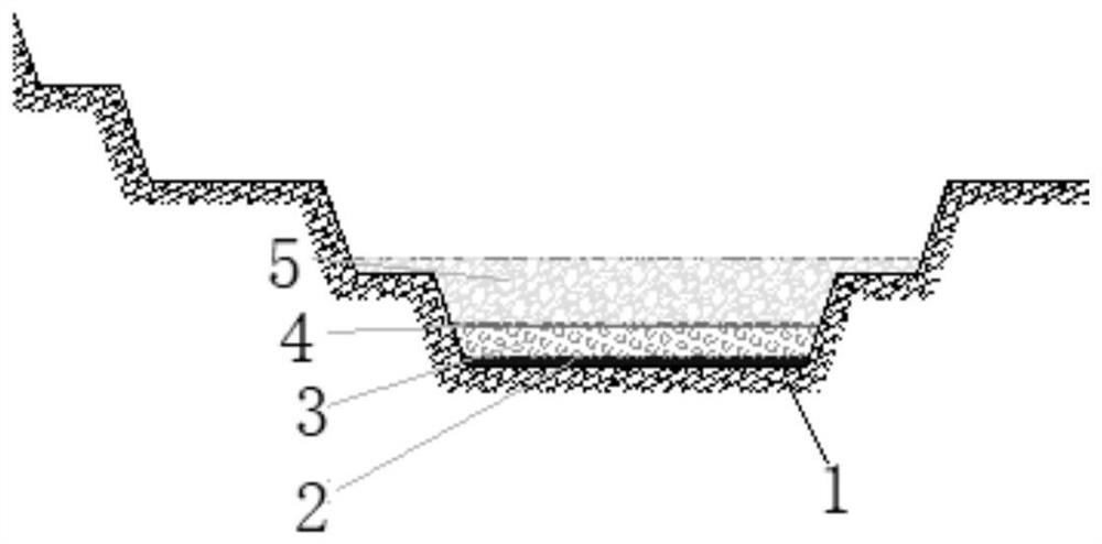
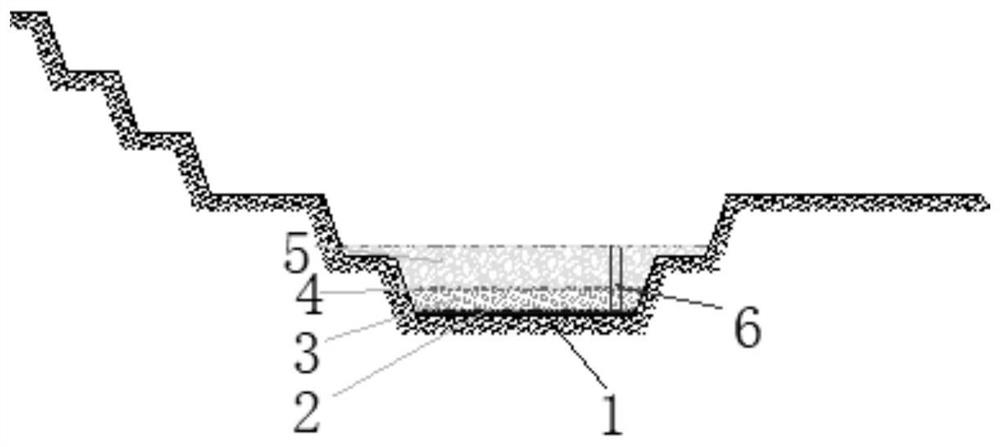
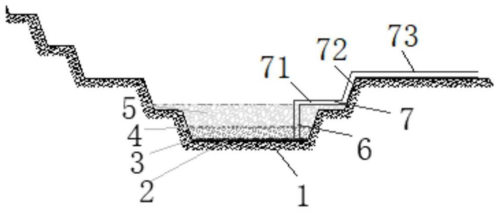
[0037] A kind of dredging well and its dredging method at the bottom of the depression pit of the inner dump site of this embodiment, such as Figure 1 to Figure 4 As shown, the bottom of the pit 1 includes a backfill layer 2, a large filter layer 3, a permeable geotextile 4 and a waste rock layer 5 arranged sequentially from bottom to top; Well 6, the water outlet of the draining well 6 is located outside the waste rock layer 5; it also includes a drain pipe 7, the water inlet end of the drain pipe 7 is connected with the water outlet of the draining well 6, and the water outlet extends Beyond the slope of the dump site.

[0038] Such as figure 1 As shown, the backfill layer 2 is provided with multiple layers, and each layer has a thickness of 0.5 to 1.0 meters. Each layer is tiled at the bottom of the pit 1 to form a water catchment area. Large block water filter layer 3, the thickness of the large block water filter layer 3 is not less than 0.5 meters, forming an artifici...

Embodiment 2

[0047] A kind of dredging well and its dredging method at the bottom of the inner dump pit of the present embodiment, the basic structure is the same as that of embodiment 1, the differences and improvements are as follows: Figure 1 to Figure 4 As shown, the method for drying at the bottom of the pit 1 of the inner dump site includes the following steps:

[0048] Step 1, treating the bottom of the pit: laying a backfill layer 2, a large filter layer 3, a permeable geotextile 4 and a waste rock layer 5 on the bottom of the pit 1 from bottom to top;

[0049] Step 2, arranging drainage wells: a drainage well 6 is vertically arranged at the backfill layer 2, and the drainage well 6 includes a well wall pipe, a filter pipe and a sedimentation pipe connected in sequence, and the outlet of the sedimentation pipe extends out of the waste water. Outside the stone layer 5; and a deep water pump is arranged in the well to pump out the accumulated water;

[0050] Step 3, arranging the d...


PUM


Abstract

The invention discloses a drainage well for a sunken pit bottom of an inner dumping site and a drainage method of the drainage well, and belongs to the field of mineral engineering. The sunken pit bottom comprises a backfill body layer, a large water filtering layer, water-permeable geotextile and a waste rock layer which are sequentially arranged from bottom to top, wherein the drainage well is vertically arranged at the backfill body layer, a water outlet of the drainage well is located outside the waste rock layer, the sunken pit bottom further comprises a drainage pipe, the water inlet end of the drainage pipe communicates with a water outlet of the drainage well, and the water outlet end of the drainage pipe extends out of the side slope of a waste dump. According to the drainage well, by reasonably treating the pit bottom, an artificial permeable layer is formed, the drainage well is arranged in the treated pit bottom by adopting the drainage well with a complete well structure, the drainage pipeline is arranged in an inclined shaft manner, and finally gushing water at the bottom of the sunken pit is drained out of the inner dumping site; and the drainage well can reduce the work amount of pit bottom treatment of the inner dumping site, save investment and reduce the pit bottom treatment time.

Description

technical field [0001] The invention relates to the field of mining engineering, and more specifically relates to a draining well at the bottom of an inner dump pit and a draining method thereof. Background technique [0002] Ejection using the mined space is called internal drainage. Generally speaking, mines use the space in the existing stope that has reached the final stage of design, without affecting the existing mining system, and discard the stripped materials in the nearest stope, thus forming an internal dump. [0003] With the backfilling of the internal stripped material, the slope steps of the inner dump site will gradually rise, resulting in the long-term accumulation of atmospheric precipitation and the surrounding underground aquifer at the base. At the same time, the higher slope steps will block Atmospheric precipitation and the leakage of water gushing from the surrounding underground aquifer, etc., caused the gushing water to seep into the inner dump, wh...

Claims


Application Information

Patent Timeline
IPC IPC(8): E02D3/10E02D19/10E02D19/20
CPCE02D3/10E02D19/10E02D19/20
Inventor 陈洪王春仁赵迎贵陈海孙立君
Owner 马钢集团设计研究院有限责任公司
Why Eureka
Try Eureka